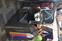
The pedal assembly that came with the machine was some sort of aftermarket conversion deal that had been unceremoniously cut into the original cab. After removing it, there was an irregular looking hole – not good:
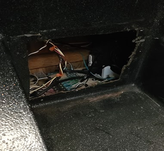
Figure 19: A rough and janky hole. No jokes here, please!
From what I could tell, though, that hole didn’t really hurt what we wanted to do. The pedal assembly is mounted horizontally – it sits on the rest of the cabinet there (the horizontal part that wasn’t modified), with the top end of it mounting to the cab in the area where the hole sits. I thus made a steel plate with holes that aligned with the ones that were there (for the aftermarket pedal assembly), painted it black, and used it to cover the hole (later putting a few additional mounting holes into that plate to accommodate the top of the pedal assembly).
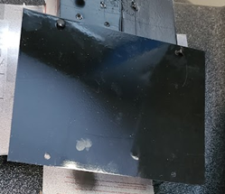
Figure 20: Simple sheet-metal plate, spray painted black, to fill the hole.
Now, the missing assembly I needed was the Atari AA006315-01, the early kind used with the upright version. This setup was common in early Atari driving games – the pedal is spring loaded and activates a simple switch. I knew I had a bunch somewhere, but they were in storage (sigh) – so I ordered a spare one taken from a Sprint 2 machine from Quarterarcade.com:
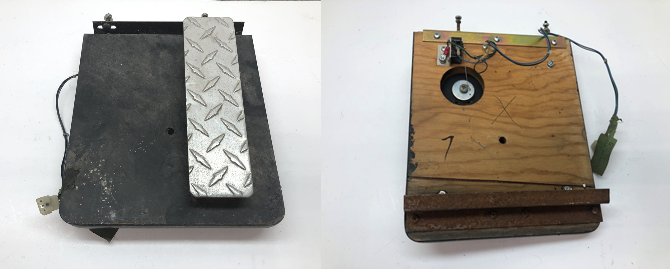
Figure 21: Pedal assembly. Pretty simple, by any measure, and this one was a little rusty!
The unit was complete but pretty dirty and rusty. I took it apart carefully and soaked any of the parts that were rusty in Evaporust for a few days. Once the parts came out of the tank, I rinsed them and dried them off with paper towels. For the black metal plate and a few of the other parts, I spray painted with flat black Krylon. The wood got scrubbed. The switch got a good bath in contact cleaner and was tested using a multimeter. We crimped on new connectors, of course, as the old ones were corroded. It didn’t come out perfect (could have sandblaster and powder-coated), but was fine:
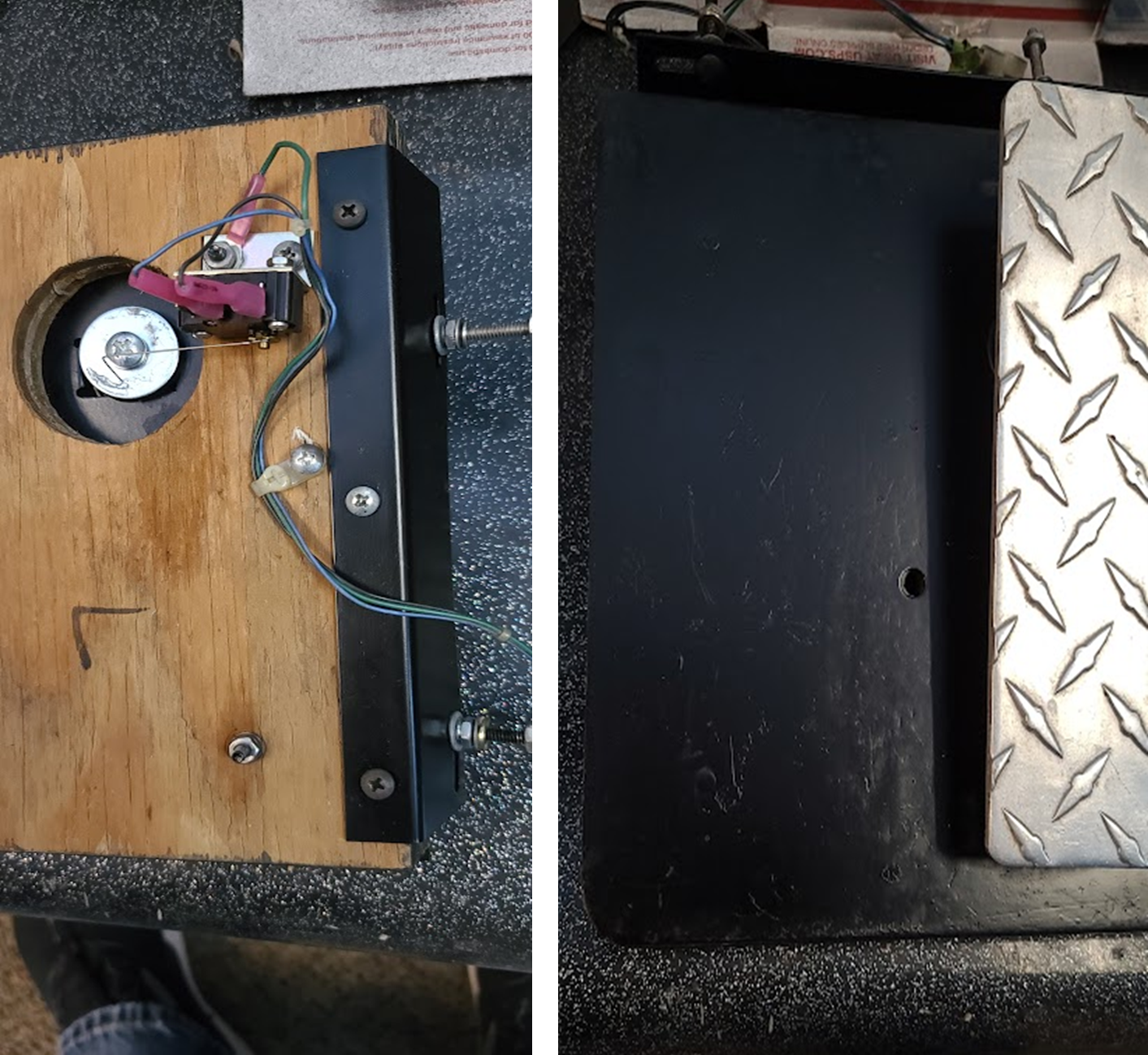
Figure 22: Much cleaner!
Note that I had to remove the metal bracket toward the bottom underside of the assembly, as the wood seems to sit right on the ND fiberglass from what I can tell. To attach the pedal at the top of the assembly, I placed it on the machine, marked the spots where the holes should go to keep the pedal in position and at a slight angle, and drilled away. The pedal mounts with a couple of screw/washer/nut combinations to the metal plate we made, and the harness wire goes underneath and through the plate into the machine. Unfortunately, I didn’t drill the holes in exactly the right spot to get the bottom of the pedal to sit on the fiberglass – I went a little too high. I had to attach another small block of wood under the pedal to get it solid, then mounted it, and it came out fine: