The ND cockpit has a shifter panel on the right-hand side that is supposed to support both shifting and game selection. When I took mine off, however, it was a huge mess: someone had removed the game selection control AND cut out the shift control hole in the panel to fit a larger two-way aftermarket part. On top of that, they painted over the artwork with a crappy black spray. Not good.
I took the panel apart, figured out from the ND manual that the game uses a four-way Atari gear shifter A000608-08 (see here), and dug one out from the parts stash. Sadly, the one I had a number of issues, thus I ordered another donor from Ebay to assist with the rebuild. To rebuild it, I down selected a set of parts from the multiple controls, then washed all of the plastic parts in clean water w/dish soap and dried off. I put the whole thing back together, lubricating with SlyGlide at the key points. Normally Atari used something called Nyogel, and while you can still get similar or NOS bits of that stuff, I’ve had good luck with the Slyglide…and you can get that stuff at most auto parts stores. The control went back together, and while it was/still is a little stiff, I think it will work out ok and “break in” once folks start playing the game.
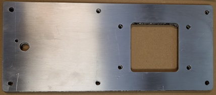
Figure 12: Repro panel with four unwanted holes that we skipped on second revision.
The shifter was the easy part, though – it was the butchered control panel that was the sucky part. Using the butchered one and the rebuilt control (for ensuring the new hole was right) I had a friendly machinist do a repro on a CNC mill – files available here. He cut it, then tumbled it in a media tumbler to get a decent finish, and it came out pretty well. Sidenote: we actually did it twice because he/we initially thought the four holes around the shifter opening were important – turns out they were part of (poorly) retrofitting the alternative shifter in there, and not a part of the original Atari setup. The second panel didn’t have the extra holes, as we wanted it to look original.
Of course, the new panel lacked the artwork, and nobody is making repro stickers for the rare ND cockpit, so….what to do? I could see the art through the black paint, but it was a little messed up in spots. As a non-destructive “first pass” I put the old panel on a flatbed, scanned it under a bunch of different settings, then played with photoshop to see how clean I could get it. It was kinda tough, and there were spots I was hoping might be better IF only I could get the paint off.
Thus, given I had the backup scans and could do no better at this point with common tools, I took a little goof-off, put it on a red shop towel, and rubbed a little over the black paint. A tiny bit of the paint started to come off – but not quite enough, and I was concerned if I applied too much goof-off or chemical it would take up the underlying sticker. I tried a simpler method – gentle scraping with a plastic edge. I worked carefully around the panel, a little at a time taking off paint chips. When I went over the areas with the art I was very gentle, and the paint seemed to come off ok while leaving the art intact.
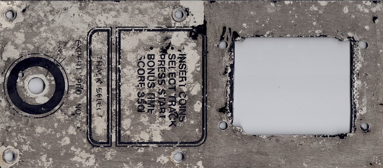
Figure 13: Butchered panel after black paint removed. Not pretty.
Once this was done, I re-scanned the art and tried some Adobe Photoshop hacking, but it was still pretty dirty. Eventually I decided the plan was to turn that cleaned-up image over to a digital artist, who used it to trace and create a new vector file (download that here). The file was now good enough to get a sticker printed at StickerMule, and I had two made just in case I screwed up applying the first one. I had the sticker made a little bigger and with a matte finish and a clear background, figuring I would apply it to the metal, trim it, and it would be good. And man, it came out pretty sweet, plus or minus my ability to get a sticker aligned correctly! 🙂
Also, interestingly, when I went to mount the standard Atari shifter onto the panel, there seemed to be some sort of spacer missing. I found this picture of spacers online, which made sense:
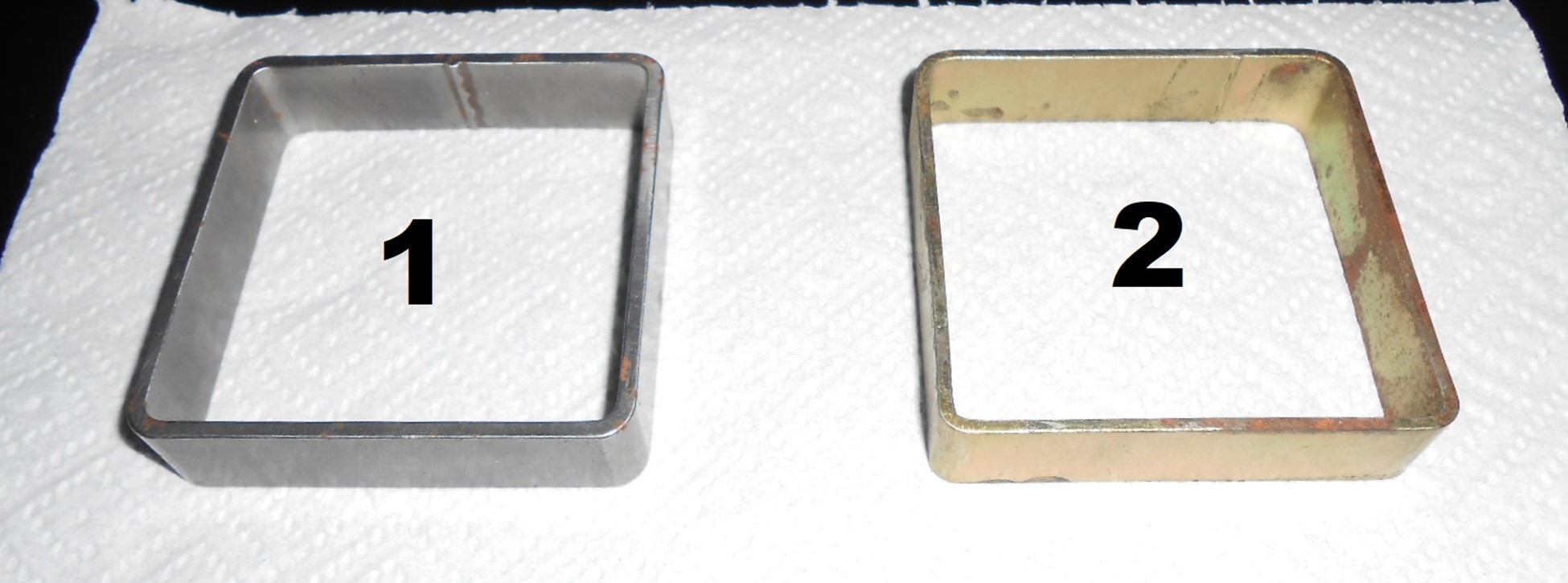
Figure 14: Spacer ring and ring repro, from a posting on KLOV.
There didn’t seem to be anyone currently selling repros of these, or NOS, thus I just worked with the machinist to come up with one – a ring of bent steel that did the trick perfectly:
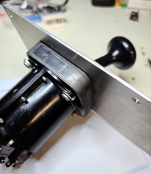
Figure 15: Spacer ring in place – fits great!
The final result wasn’t bad, and looked a lot like the pic of the unbutchered one sent by another collector:
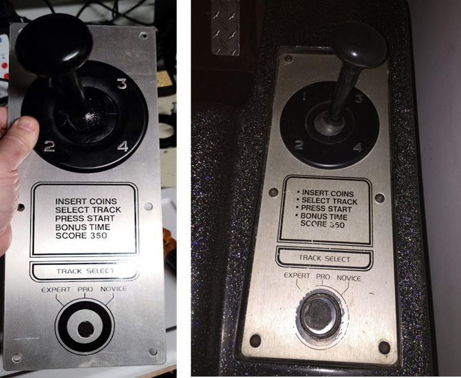
Figure 16: My brand-new panel (left), and another collector’s original panel (right).
Another missing part of the equation there was the game selector switch, which like I said, was missing. The switch lets you select between expert, pro, and novice modes, and when you look at the schematics it is just a simple multi-positive rotary switch. Unfortunately, one can’t easily find the Atari original online for sale, hence I ordered a couple new alternatives. I ended up with the Taiss Rotary 4 position switch, which fit fine BUT lacked a tab that stops it from turning if the nut loosens. I’m still working on that one. It also has one too many positions, but not a big deal.
Another obstacle on the shifter panel was how it attaches to the fiberglass cabinet. It looks to have originally used some sort of plastic push-connector that expands a rubber grommet in the hole (when pushed) locking the plate in. These turned out to be called rivet nuts, and though there are a LOT of them available online, it’s tough to find the right one. I’m also not a huge fan of the push/pull aspect and would prefer a screw head of some sort, thus I went with these, which are like shoulder grommets that draw up and expand as the screw goes into them, thus locking the panel. They seem to work, though – but if anyone out there knows a better solution, definitely email me.
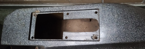
Figure 17: Fiberglass cutout area where the shifter panel sits. Not sure if it was modded from original or not – a little oddly shaped.
Something else I noticed was that the new CP seemed to sit a little lower in the fiberglass than the old one, I assume because of the mounting connectors I used. I didn’t think this was a problem so much as an opportunity: it would be worthwhile to put some shock-absorption between the metal and the fiberglass just to reduce stress on the fiberglass itself. I cut a spacer/gasket out of this rubber, and it laid just fine in that space.
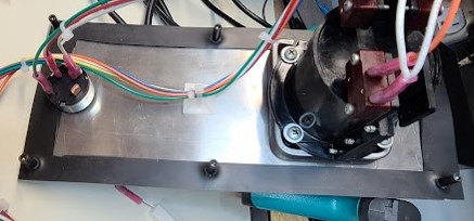
Figure 18: Simple rubber gasket cut to help shifter panel sit better in the fiberglass.
The final part of the shifter panel puzzle was the harness, but I’ll talk about that under the harness section later.