So now we have all the major parts in the cabinet, and really badly want to turn it on, play the game – right? Well, yes – but – I’m an engineer, and one thing I’ve learned over the years is that no matter how careful you are mistakes can (and do) happen. This is especially true when the project extends over months or years (how this one has). In any case, I thought through what would be reasonable initial testing, and came to three steps: basic AC power test, logic power test, and self-test. For the basic AC power test, I wanted to make sure the AC input/switch/interlock/harness/input aspects were fine and working. The first step was to test continuity/wiring before applying power – so, I made sure the machine was unplugged (obviously), then unplugging the monitor connector and the IEC power cord going into the PC power supply. I also made sure the edge connector to the PCB was unplugged. Then, I turned on the power switch (again, with the machine not plugged into the wall), and pulled the interlock button outward (to lock it in the “on” position). Then I went to use the meter to test continuity from the AC plug pins through to the monitor pins and the IEC cord end. It was at this point that I noticed the AC cord end on the machine needed a new plug (the ground pin was cut off the old one, like so many other games I’ve inherited over the years), so I went down to the stash, picked one out, and put it on. After that the continuities checked out fine, all correct. Note that I also double check polarity (line is consistent, hot is consistent) throughout.
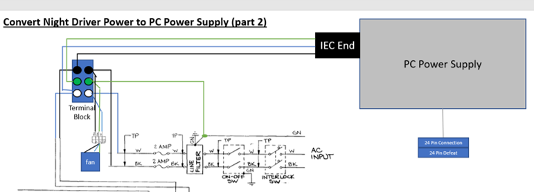
After checking the continuity, I turned off the switch, pushed the interlock back to open position, and plugged in the game. I inserted my meter leads into the IEC cord end, set it to AC, pulled out the interlock – and saw no power, which is correct. I then flipped on the game switch, and sure enough – 120VAC at the IEC end! I also noticed the fan was now running – good news. Finally, I pulled the meter leads out of the IEC (carefully), then put them across pins 9 and 10 in the monitor connector – also 120VAC. I pushed the interlock to trip it, the 120V went away, and the fan turned off. All good on this test, so I turned off the power to the game and plugged the IEC connector and the monitor back in.
The next test was logic power. With the IEC cord plugged in, the monitor plugged in, but the PCB still detached, I powered up the machine. The first thing you notice (hopefully) is the monitor coming on. In the back of the machine you’ll see a small orange glow in the neck of the CRT, indicating the heater is working and the tube isn’t shot. The second thing you should see is a white raster (since there is no signal there right now) on the front of the screen, through the plexi. In our case, all good.
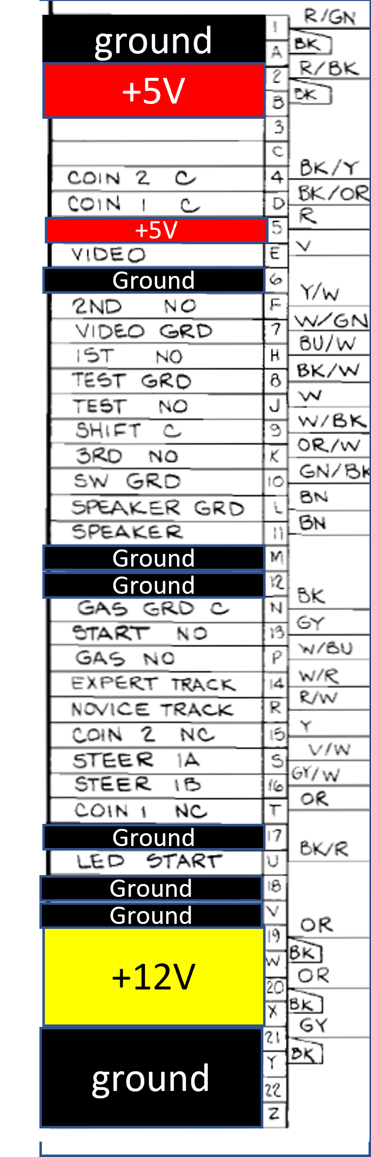
The second thing on this test is the main event – to check if we are getting the right voltages and grounds at the PCB edge connector (BEFORE we connect it to the PCB). Remember, we converted the PCB by taking the regulators and such off the PCB and wiring it to use a PC power supply, thus the pinout in Figure 93 is what we need to check with the meter. We make sure the machine is on (and the PCB fan is on), then listen to make sure the PC power supply is on. In my case it was fine – you could hear the supply fan. I went and measured, using my meter on DC volts, the voltages at the pins per the diagram. I also went and tested the voltage between the ground pins to make sure they were 0V difference (thus all tied together). All good here, so I shut off the machine, and went to the third test.
The third test was the scariest one – actually powering up the PCB and seeing if we could get some life from the board and signal on that monitor. I figured the best initial step (NASA style hehe) was to follow the procedure for self-test in the ND manual pp.19-22. With the game off, I reattached the PCB edge connector to the PCB. I set the track selector (on the shift panel) to “Pro Track,” put the gear shifter in 4th gear, put the self-test switch to “on,” and then powered it all up. AND…..AND…..nothing.
The first thing to check, of course, was the logic voltage on the PCB, which should have been very close to 5V. Weirdly, this wasn’t the case – I was getting 4.35V anywhere I tested on the board! It blew me away, because the cables should be good, connectors, the power supply should be able to supply the board current no problem, and so on. What to do?
The first step I did was unplug all the non-critical connectors – the control panels, the pedal, the coin counter, the coin door – pretty much everything except the power circuit. I did this just in case there was some unclear short or I wired something wrong. Sadly, that was not the case – the board still measured 4.35V. I had tested the PCB on a benchtop, so there shouldn’t be any shorts dragging it down (unless they were new), and the edge connector showed 5V when unhooked from the board. Hm.
I didn’t think it was a voltage problem – more that the board was current-starved. I had two hypotheses:
- The board couldn’t pull the right amount of current at 5V through the repaired edge connector, because the edge originally was at a higher voltage (and thus would have been pulling a lower current originally before my mods).
- That the circuit I was pulling from on the ATX supply (the hard drive/peripheral 4 pin molexes) wasn’t providing the current needed, for whatever reason.
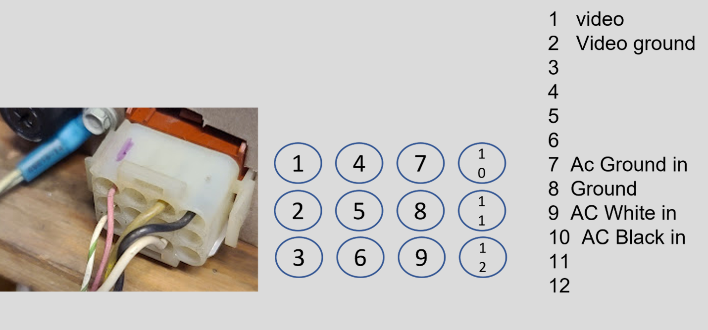
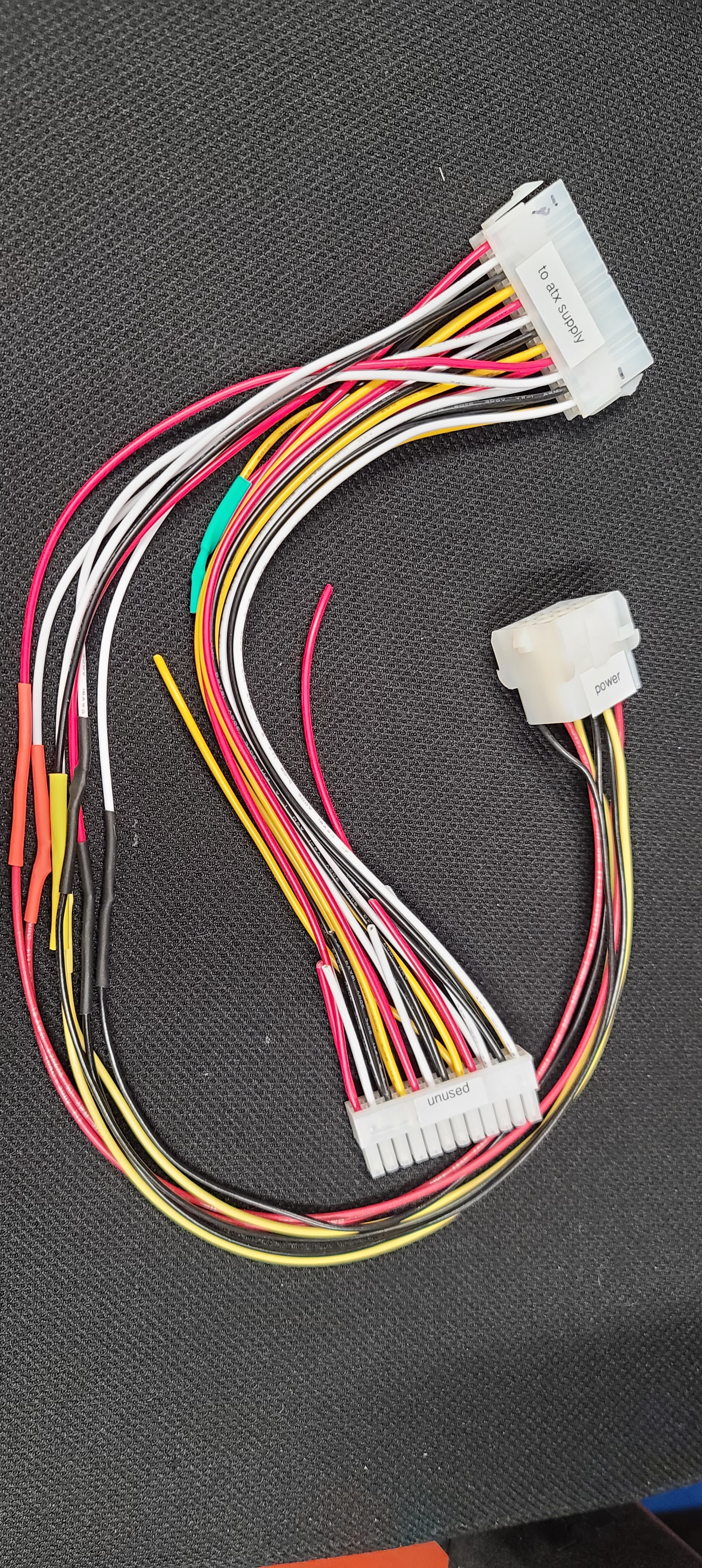
I decided to try the second direction first. Rather than use the peripheral power chain, I went for the 24 pin motherboard connector – which absolutely should be able to source the kind of current needed to run the ND PCB. To make this work, I picked up a 24 ATX power cable extension, found a female 12 pin connector shell in my pile (along with the 0.084 female pins), and built a cable ala the diagram below. Again, I always label the shell numbering (to reduce the chances I put the pins in incorrectly) and I label the function of the connector. Note that I got to skip/recover the cheat plug and put it back in my parts bin, as I just had to jumper the two pins on my new cable and it would keep the supply turned on.
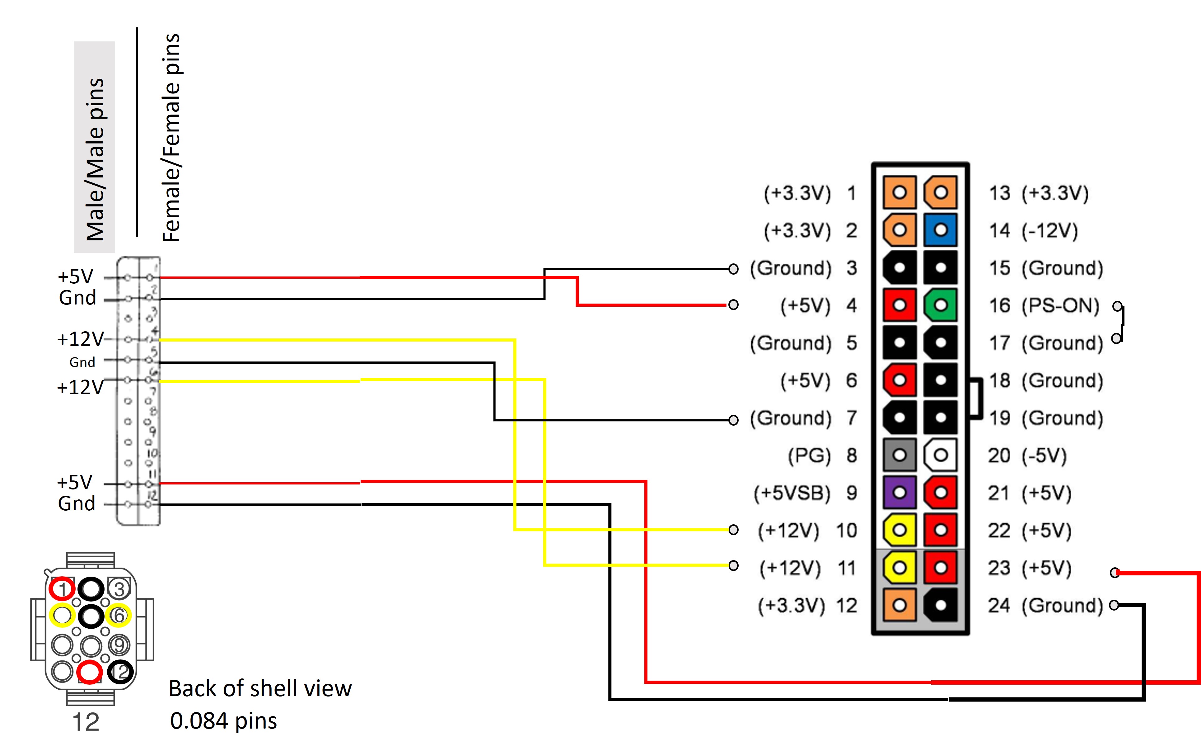
I took these in, unhooked the other cable I had in there, removed the power cheat plug, and attached my new cable to the ATX supply and ND harness. I powered it up and measured the PCB…and…
Damn, no luck.