Getting everything into the cabinet wasn’t too bad. First, we got the monitor in and bolted down. This sounds easy but when you see the situation it looks like there is no way that 23” monitor will fit in there. It turns out the trick is that you really have to maneuver the monitor inward (tilting forward and backward) while being very careful not to knock the neck into the wood cabinet. It’s a tight fit through that opening but once it is in there is plenty of room to move it around.
Second, we screw the power supply board to the bottom ala Figure 83. This is pretty easy given we’ve made the board to fit in the space allotted.
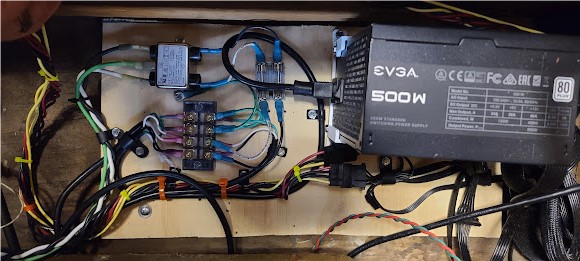
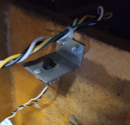
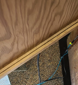
Third, we put the harness into the cabinet. Now, the harness (as we discussed) is a modified version of an upright one, thus it does not cleanly align with the cabinet, any areas where there might be a place to tie down to, and so on. It was long enough (thankfully) in all the key places, and we used P-clips and screws to lock it down where there was wood to screw to, and adhesive squares/zip ties in places where we only had fiberglass and didn’t want to pierce it. This was an iterative process where we put the harness in “loosely” – tying it down in points, leaving it hanging in others – while we mounted the other key parts and panels. We hooked up connectors to the right spots as we could, just to make sure we were getting things in place. The test switch and its little bracket also happened to be attached to the harness, so we mounted that in the cab.
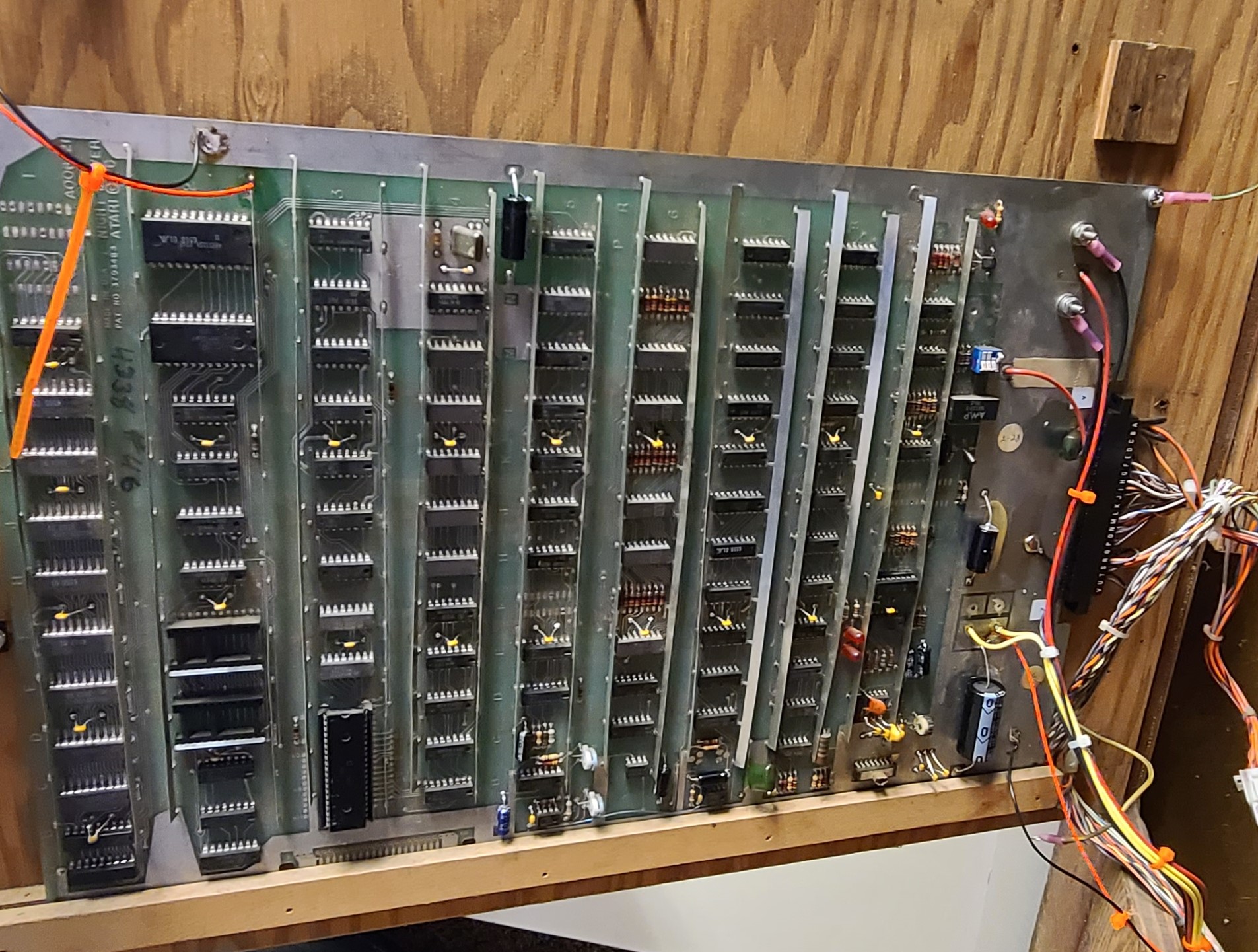
Fourth, we mounted the PCB. The PCB sits on a small wood shelf on the door of the cabinets, with the edge connector/harness running to the door at the hinge edge. The original mounting holes were clearly still there on the door, but I was missing the right screws and spacers. I picked up some new hardware and mounted the PCB in the original spot, including some nylon spacers from Home Depot, and avoiding the butchery and abuse that was the prior Top Driver PCB stack location.
Adding a Fan
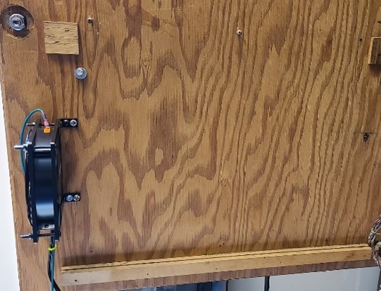
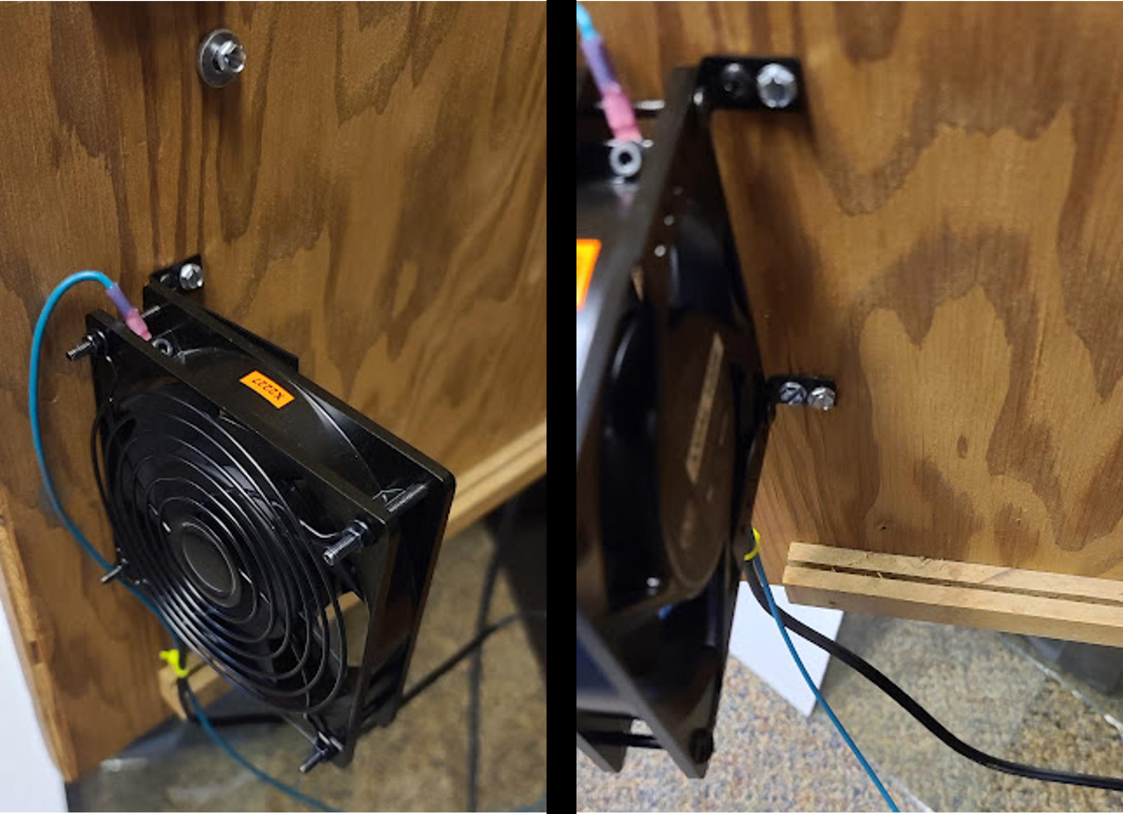
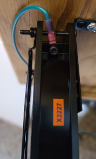
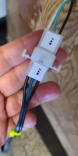
Obviously, after all the effort of getting the PCB working, you want to protect it and keep it going as long as you can. Taking the heat-generating power circuit off the PCB was a step in the right direction; another step is to do whatever you can to keep the rest of the chips cool. The cabinet has some ventilation but any airflow is completely passive, thus I thought it would be good to add a simple muffin fan to keep the PCB a little cooler. So I took the PCB back off, ordered a quiet 120VAC muffin and with some simple mounting brackets, and mounted it so that it would blow across the entire PCB. The AC cable (including a ground) ran back to the terminal block on the power board, so whenever the machine was turned on and the PCB powered, the fan would also be on. Note that when you hook up these fans, they tend to come with an odd little connector (that carries the two AC lines) and a screw, and you are expected to screw the chassis of the fan to ground – which isn’t 100% necessary, but it’s absolutely good for safety purposes.