Prolog: Can’t Get it (the logic rail) Up!
Aw man…..
So, I got to the point where I was testing the PCB in the game, a whole mess-o-stuff came to light. What started to unravel this whole ball of wax was when I plugged the game PCB into the harness in the machine and couldn’t get the voltage to come up to 5V. It was pretty frustrating, so as I took a few different steps in trying to troubleshoot the problem:
- I unhooked everything on the harness except the PCB and power connectors, guessing that maybe something else was shorted/dragging down the 5V. This didn’t change the voltage on the PCB.
- I double checked the fuses on the AC line feeding the ATX supply, and figured out that I really needed more like 10A fuses there (not 3A). I figured this might have been starving the ATX supply, so I replaced and retried – still, the voltage was very low.
- I looked at the edge connector and found my copper foil repair had failed and I was likely trying to put a bunch of current through a very small connection. I thus went and soldered a special custom power harness with a 9 pin Molex to the PCB, which enables me to get the power to the PCB without going through the edge connector. This also meant building a matching hardness to connect the 9-pin to the outputs of the ATX supply. I wired all this, tested it, and still found less than 4.5V on the PCB! DOH!
- I figured I might be trying to draw too much through the 4 pin peripheral connectors on the ATX supply, so I ordered an extension for the 24-pin connector and hacked that until it connected the 24 pin output to the 9 pin power. Powered all of it up, and the same thing – like 4.5V on the PCB!
- As a “last ditch” effort with an ATX supply, I took out a completely new, fresh one (unused), plugged it into the 24 pin to 9 pin cable, attached an IEC cord, and plugged that into the wall. This bypassed all my input wiring, the fuses, everything – it was ATX à cable à PCB. And STILL – I had like 4.5V!
Enough was enough, folks – what the hell was the problem? I took the PCB out and put it back on my test-bench. Because I was no longer putting the power through my edge connector (thus jamma harness wasn’t going to power it) I took a cheap arcade supply, built yet another power cable with a 9 pin molex, and set it up. FINALLY, the voltage came up to 5V without an issue. SOMEHOW I WAS MISUSING/UNDERSTANDING THE ATX SUPPLIES! To this day I have no idea what the deal is – that somehow the PCB wasn’t sufficient load on the switching supply, or I was hooking it up wrong, or what – if anyone has an idea, please share!
ROM Mapping PCB: A Success, or Just Suck?
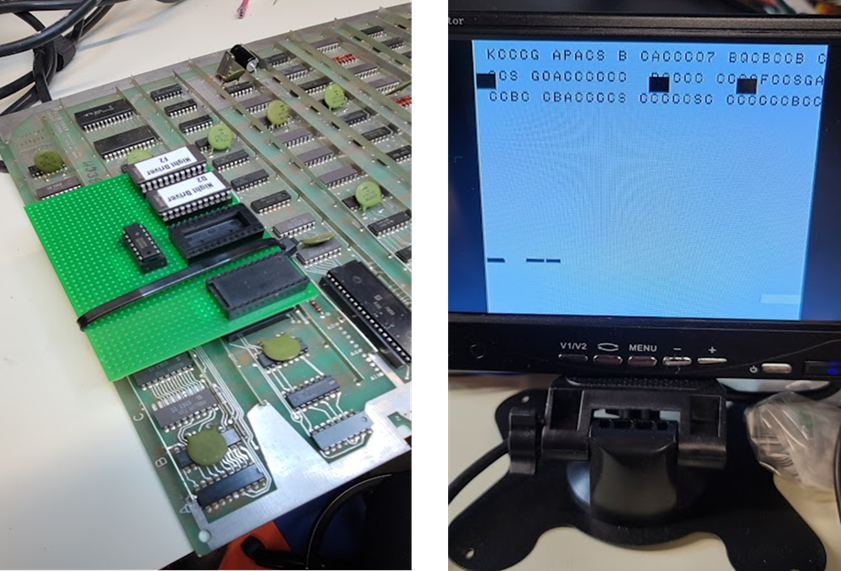
But now, I had a different issue – the PCB started flaking out when I secured the adapted PCB to the main PCB with a wire tie (to ensure solid attachment). After a few days of poking around, I still couldn’t make progress – the board just kept watchdogging and spitting the same garbage, consistently, without fail:
It was then I decided to program another solution that would eliminate the ROMs on the board and hijack the bus to another, single ROM sitting next to the 6502 (for those of you that remember the console Game Genie, same idea) – heck, if there was a bad line, or socket, or whatever, this new approach would fix it. I had picked up a cool little “universal” solution here (thanks Brian!), but to use it (go after the new approach) I had to dig for the memory map. I went online and found this:
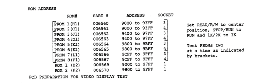
Huh. How would you have two sets of memory covering the same memory space? Was this some sort of poorly documented bank-switching craziness? Was I reading it wrong? How to handle? Well, I went back to the original Night Driver manual, started looking around, and remembered that, like in many manuals for the older games, there was a “Theory of Operation” section. And in that Theory of Operation, I found this:

Eight 4-bit PROMs, operating in pairs (covering high/low bits), OR two larger 8-bit ROMs handling the whole space. SO – I went down to my bench, looked at the PCB, discovered, INDEED, I had an older revision of the PCB and the smaller ROMs were there:
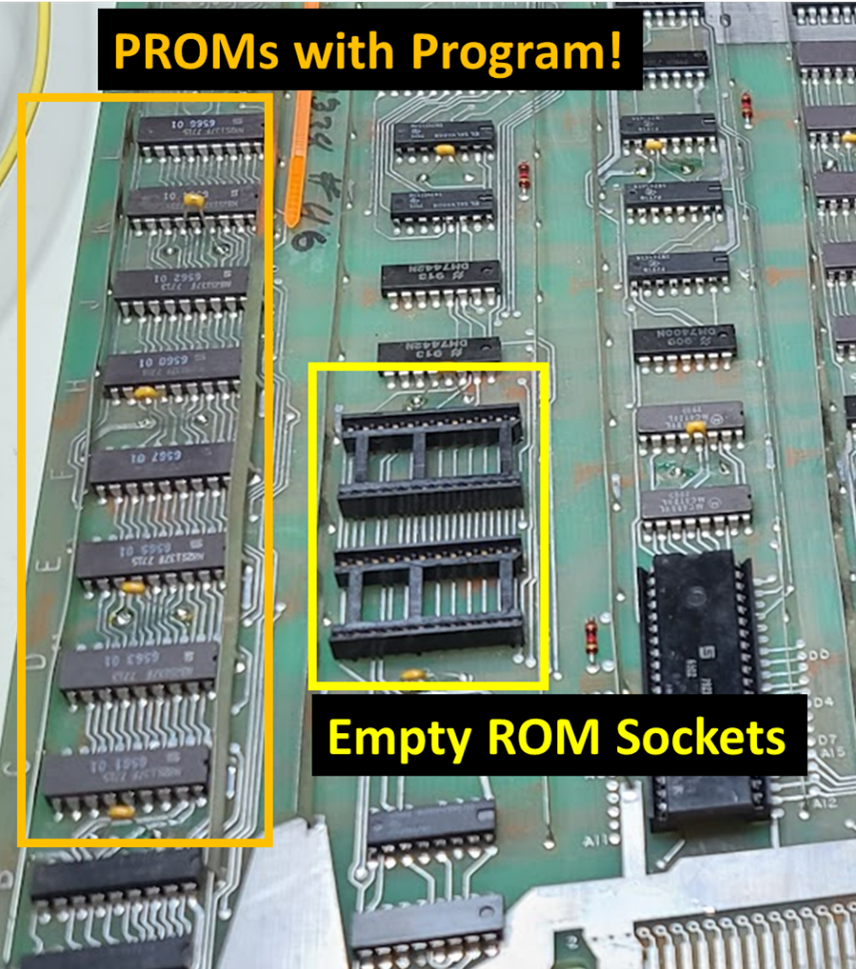
Those sockets were supposed to be empty! I pulled my adapter PCB entirely, powered it on, and lo and beyond, Night Driver! The less learned here was, like Murphy’s Law, the Golden Rule, and all other good core rules of thumb, if I had just respected the rule and READ THE ****** MANUAL up front I would have saved a handful of parts, a weekend of work, and truly head-slapping moment of embarrassment! All I can say is: DOH!
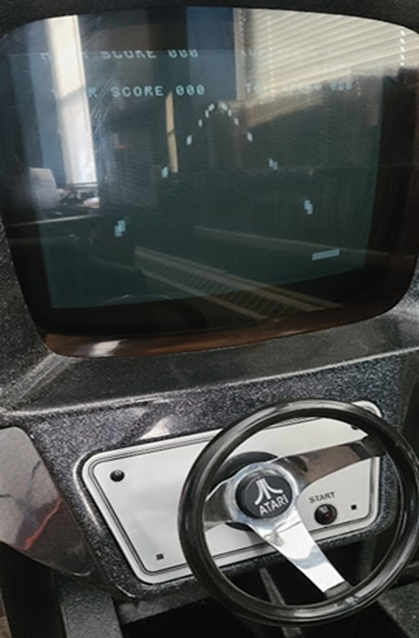
Replacing the Power Supply, Redux
In following along with the prior notion of respecting the basic laws (that of Murphy, RTFM, and so on) I looked clearly at the power situation and said – if it ain’t broke, don’t fix it. I thus decided to pull the ATX supply from the machine and replace with the nice, solid, simple, cheap arcade supply. To do this, we removed all sorts of stuff – the ATX supply, its mounting bracket, the pretty tie-downs that were holding the connections coming from the supply, and so on. For the arcade supply, I needed two cables. The first was the one that connected the supply to both the PCB (the direct connection) and the wiring harness (for the rest of the stuff). The second was the AC cable that connected the fuse/terminal block to the arcade supply. – didn’t take a picture that night, but later put the PCB back in the machine, along with an – and though it’s not yet tuned, and there’s glare, I wanted everyone to see that, yeah, it works: