The Mechanism
Where to even begin on this one? At first I thought maybe this was complete and in good order other than having someone attach the wrong wheel. After all, it has the Atari panel, and the Atari button, and fit the cabinet. Must be generally ok…right?
Red Herring #1
Oh how wrong I was. It turned out that not only was the steering wheel incorrect, but the entire underlying mechanism was something that didn’t match with anything I could find online:
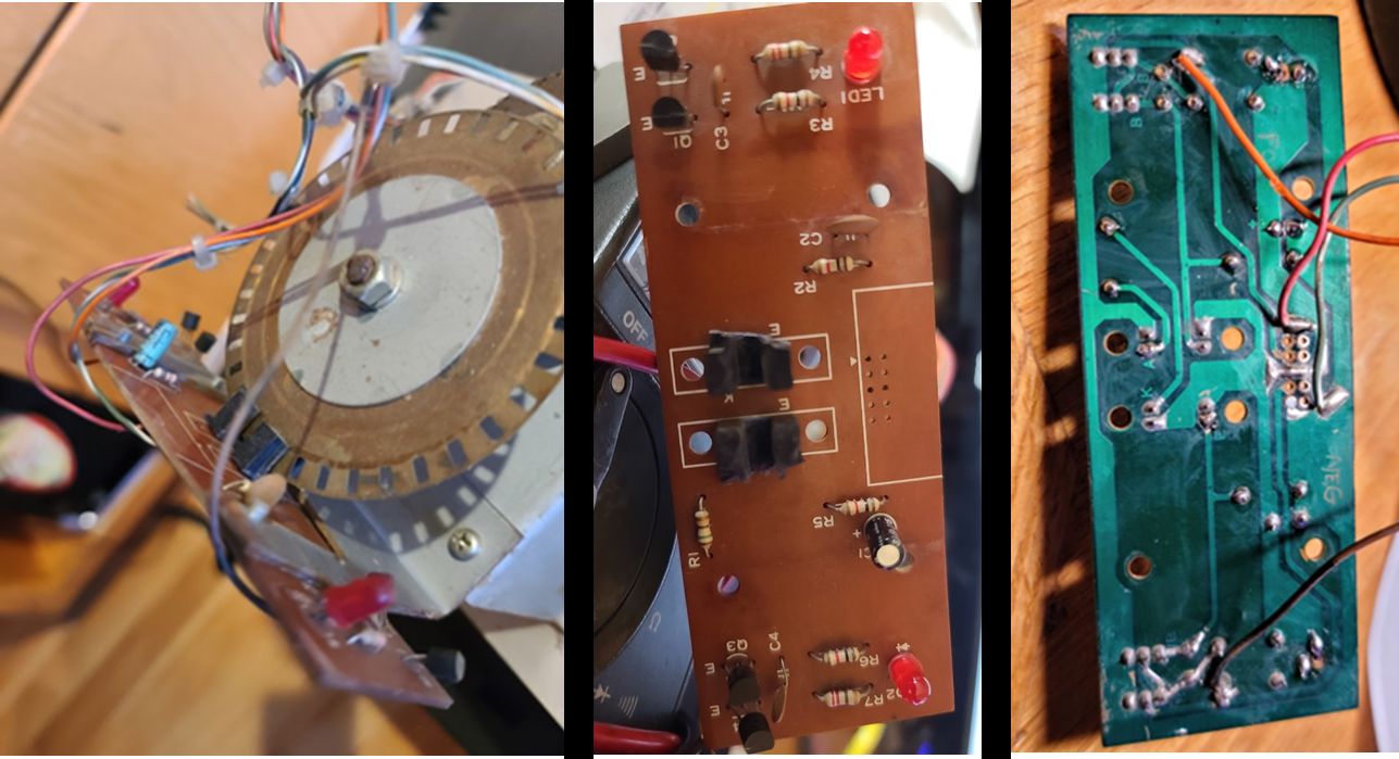
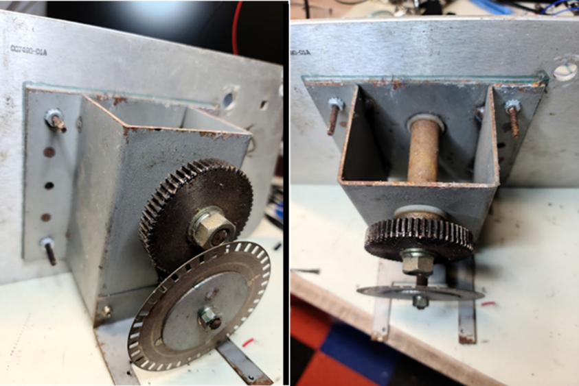
Figure 30: Back of steering mechanism that came with the game. An odd duck!
While this looks like an Atari mechanism of some sort, I could not find any reference in any Atari manual to something that looked exactly like this (or close to). The opto PCB also didn’t have any markings that I could discern, and the schematic (which I started to reverse engineer) didn’t align with what I could find in any Atari manual. Even given all this, the gear mechanism looks VERY close to some of the Atari stuff:
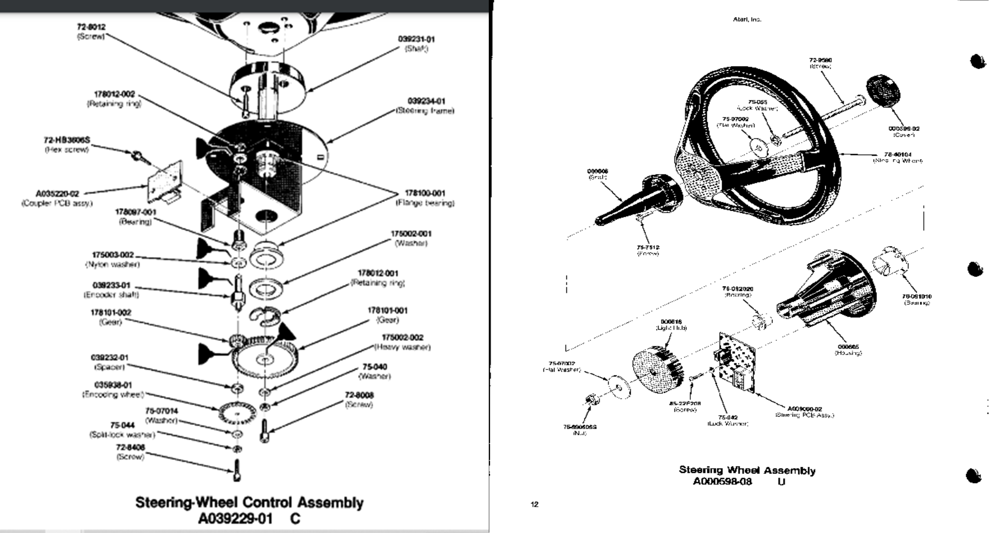
Figure 31: Two different Atari steering wheel assembly blowups.
I thus assumed MAYBE it was some sort of variant that appeared in ND cockpits and rebuilt the mechanism I had. I took a bunch of pictures as I disassembled, which is particularly important when you don’t have a reference diagram in a manual like the one above. I like to take them step-by-step ala:
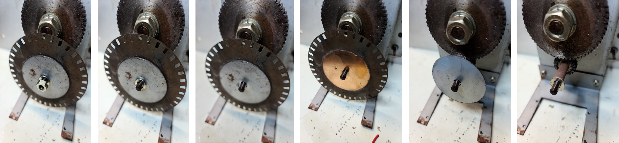
Figure 32: Taking apart the assembly that came with the machine, one step at a time.
I have learned through painful experience that documentation is essential if you hope to put it back together correctly when the time is right. In any case, I soaked the parts in Evaporust (to remove rust and paint). While they were soaking, I cleaned the PCB with rubbing alcohol and a spare toothbrush in a plastic shoebox. I also replaced all the electrolytics, traced the wiring, and came up with the following rough schematic:
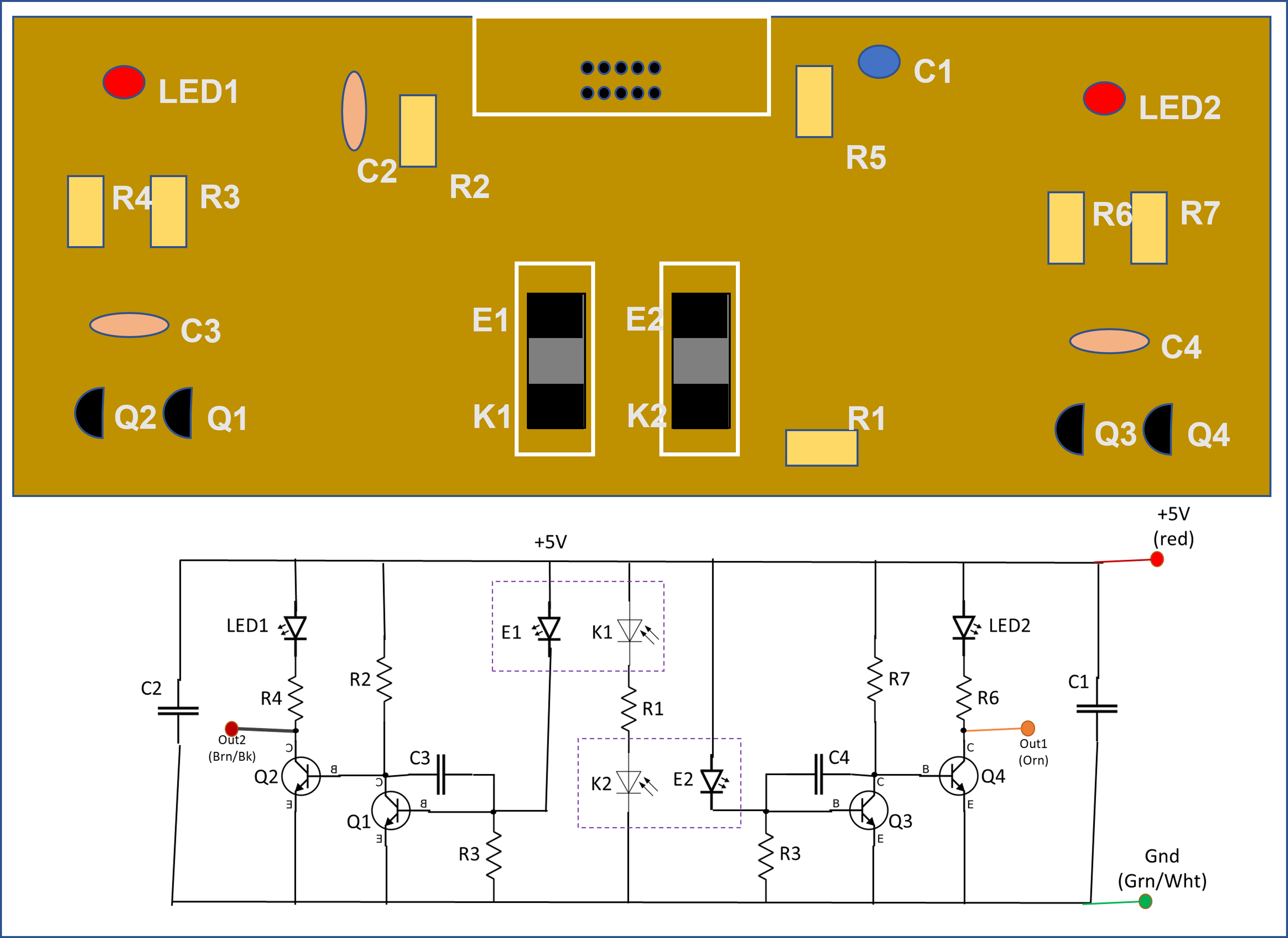
Figure 33: PCB part layout and schematic of unknown opto PCB
And if you do a quick comparison with the Atari opto schematic in the ND manual, you find there are similarities, but also differences:
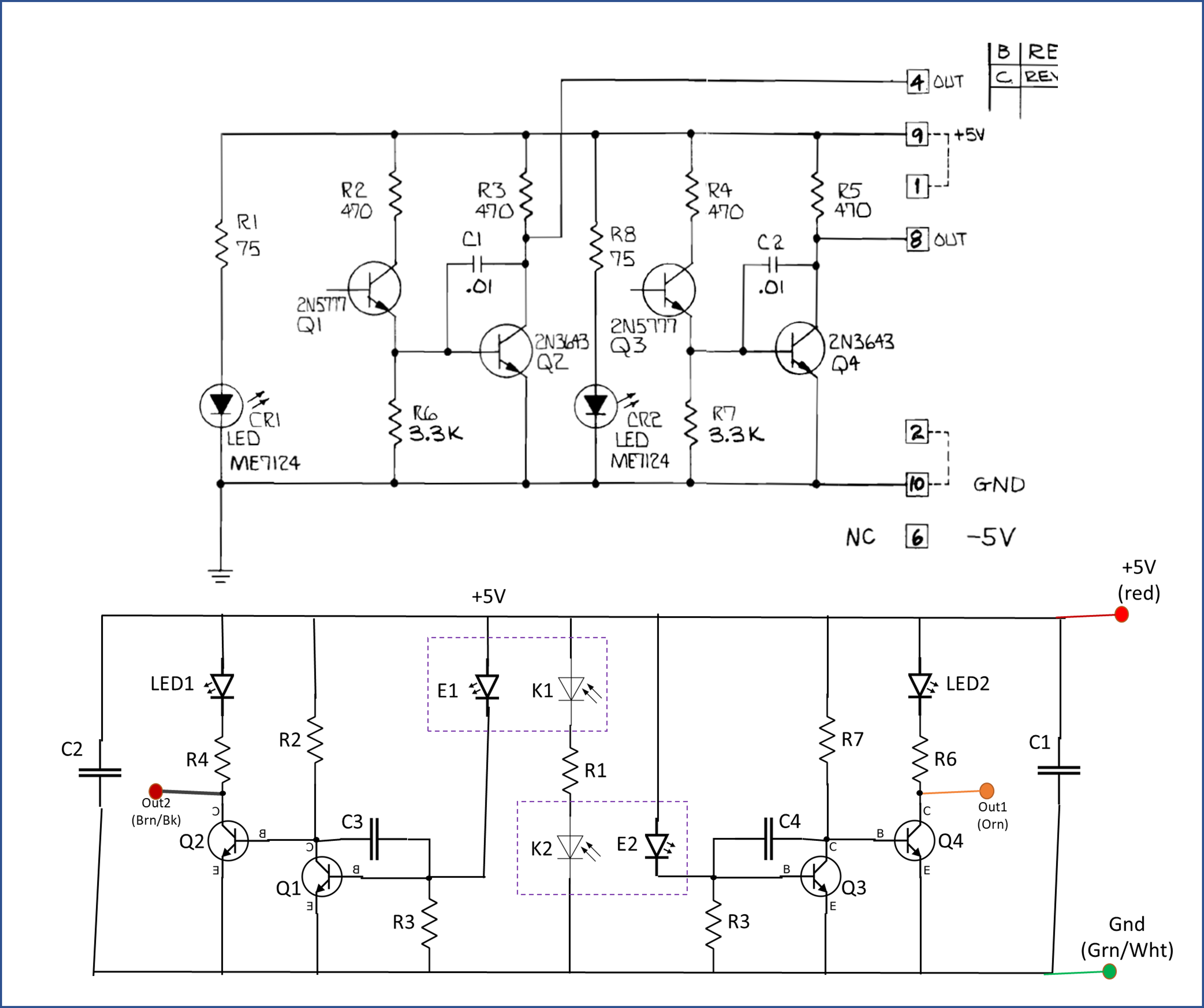
Figure 34: Comparison of opto PCBs. (Top) from ND manual (Bottom) unknown unit
The parts list for the odd opto board is:
| Part | Board |
| R1 | 150 |
| R2 | 1000 |
| R3 | 1000 |
| R4 | 220 |
| R5 | 1000 |
| R6 | 1000 |
| R7 | 220 |
| R8 | |
| C1 | 3.3 uF 50V electrolytic |
| C2 | .1 uF ceramic |
| C3 | 0.0022 uF ceramic |
| C4 | 0.0022 uF ceramic |
| LED1 | |
| LED2 | |
| Q1 | C1815Y |
| Q2 | C1815Y |
| Q3 | C1815Y |
| Q4 | C1815Y |
| Opto_Emit1 | SPX 5129-1 |
| Opto Receive1 | |
| Opto_Emit2 | SPX 5129-1 |
| Opto_Receive2 |
I cleaned up that odd opto PCB per above, connected a 5V source, and tested by moving an encoder wheel through the optos. It worked (the LEDs on the board reflect open/closed states). At least that part is good.
I then took all the mechanical components and put the mechanism back together. It all looked nice, clean, turned beautifully (after some lubrication):
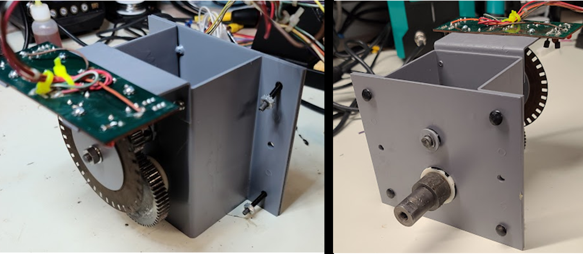
Figure 35: Weird steering/opto mech rebuilt and ready to….go?
Looks good, but to take the next step we have a conundrum:
- The steering panel has the holes for the mechanism, and there is also a large scraped-up circle around the mounting hole. Where did that come from?
- The steering wheel that came with the setup is clearly not the right one; the right one is a “500” wheel common to many Atari games.
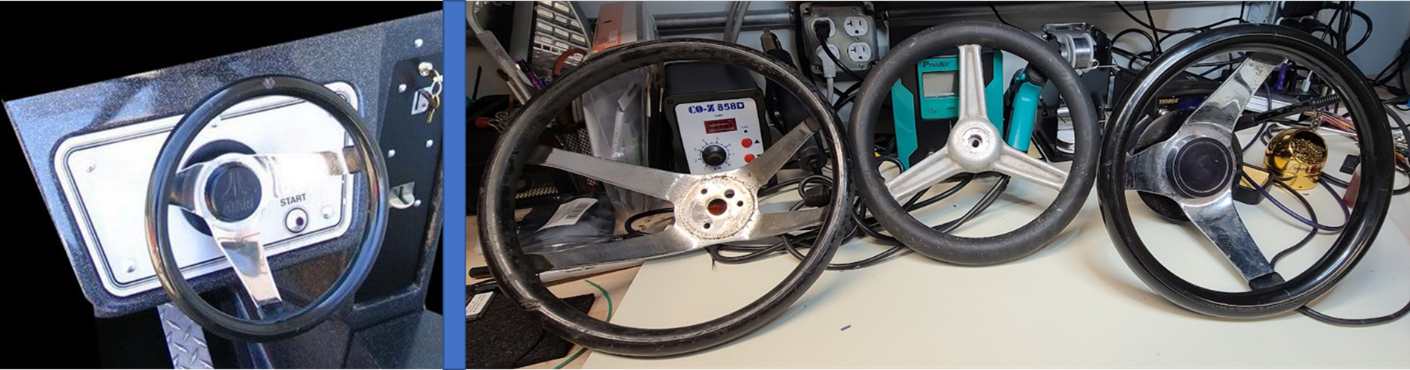
Figure 36: Reference picture of a ND cockpit steering panel (left), and the three choices I had kicking around (right). The middle wheel came with the ND cockpit and the weird mechanism but didn’t fit correctly. The other two wheels were from Atari panels of the same vintage.
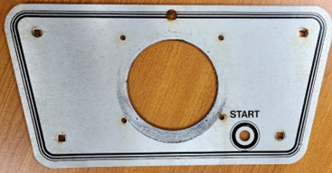
Figure 37 The steering control panel – check the weird scrape marks!
So, in looking at the reference pic, clearly, I didn’t have the correct mechanism and had just wasted a week of effort. Damn!
Red Herring #2
I went back to the drawing board, looked at the other Atari mechanisms, and figured it must be one more like the righthand – there’s a three-spoke wheel, a large circular mount plate, and something that looked like a spot where an Atari sticker might go. This one is actually a A039229-01, apparently used in Pole Positions at some point. I thus picked one off Ebay for about a hundred bucks, took it apart, cleaned, replaced a broken gear with a new one (178101-001, see here), reassembled, lubricated, and put on a new opto PCB (from here – these were made by ArcadeJason, who has a pretty interesting Youtube channel to watch when you’ve got a beer in hand) and figured I had it licked….
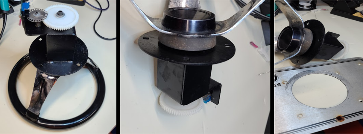
Figure 38: Second mechanism I rebuilt. (Left) Detail showing mechanism with new gear (middle) Top showing metal mounting ring (Left) View showing metal mounting ring next to old panel and scrape marks.
….until I went to mount it on the panel. Yeah, no, the holes didn’t actually align properly for that one, and it didn’t feel like the mounting ring was going to cover that scraped up portion of the panel. Really? REALLY? I’m an engineer, and now I’ve rebuilt not one but two of the wrong steering setups. The first one I don’t think was Atari (though copied to some extent). The second was Atari, but a later iteration of their steering mechs. What was I missing?
I took a closer look at the Atari mechs of the right vintage, and looking at the diagram of A0000598-08, it had potential – but I still couldn’t imagine the scraping on the panel, etc… I reached out to another collector and had him take some photos from the inside of the machine, and it showed this:
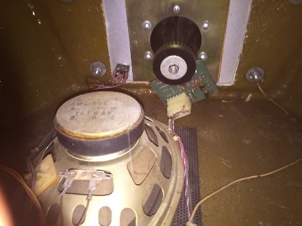
Figure 39: Inside of another collectors machine – see THE STEERING MECHANISM?
The Right One
Clearly the answer was the A0000598-08, and I went to my stash and pulled one off another vintage CP that I wasn’t using. In retrospect it makes complete sense – ND was a 1976 game, and the mechanisms used would have reflected that era. The second herring was used in Pole Position, which was five years later thus Atari would have redesigned/improved by then. The first herring I did consider might be part of a limited run Atari setup used in ND cockpits that I have yet to see in any documentation – but, the mounting holes on the CP were a little rough, and that should have tipped me off.
Anyway, I disassembled, washed the plastic parts, cleaned the metal parts, and put the 598-08 back together. There were some fun elements to this one, though. First, this mechanism uses white nylon bearings that wear down, a plastic encoder element that can get bent up pretty easily over time, and so on. Fortunately, there are folks online selling NOS or repro kits for these setups. Check out here which includes the bearings, a housing, some screws, and a spacer (but not the encoder). I used a NOS encoder wheel and NOS bearings I picked up from Ebay as a kit.
Second, mounting this beast to the thin metal CP requires a metal mounting plate and a spacer to work in conjunction with the plastic housing. I hadn’t seen the link above at the time to get spacers, thus worked with my machinist pal to 3D print one – file is here in case you want to do the same.
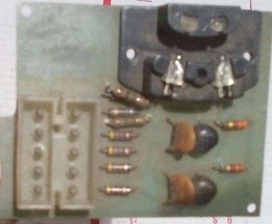
Figure 40: Old-style Atari opto PCB, parts side. Image cribbed from web – apologies to whomever took this! 🙂
Third, the opto PCB is an old-style one that uses two tiny screws to hold it in place. It also has two connectors – one older-style Molex-ey one, and a one-sided edge connector. I have no idea what the one header-type is (any tips appreciated), but the edge connector is a relatively easy one to find. I ordered the EDAC 305-012-500-202 12 position edge connector from Digikey.
Poking around with my meter, I verified the pinout as:
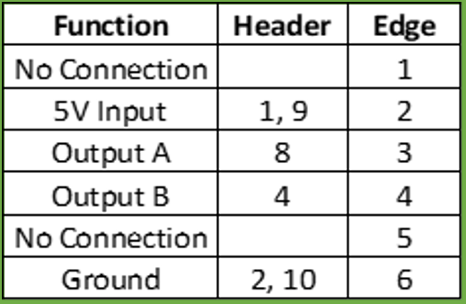
Figure 41: Old-style Atari opto board pinout.
Which is going to be important when I build the harness. In the interim, I washed the opto board with alcohol, a toothbrush, and some Q-tips, then hooked it up to a 5V source and ran an encoder wheel through it while the outputs were on my scope. Worked fine.
I took a close look at the mechanism, and the panel, and the steering wheel, and it looked like this was going to come together this time. Two aesthetic issues still needed to be addressed. The first was the steering wheel itself. The wheel was in good physical shape but had some light rust and pitting in the chrome, and the rubber felt like it might be deteriorating. Interestingly the steering wheel was “The 500” by Superior Products, which is still around and making versions of these. I thought about buying a new one but they are pretty pricey. You can get used ones off Ebay and other spots, but before I did that I tried my hand at restoring one of the ones I had.
For the rust, I picked up chrome polish from an auto parts store, used fine steel wool to take off the top layer, wiped on the polish, then used a Dremel with buffing wheel. It did ok, if not great – but at least got the rust off. I think I could revisit this if I wanted to and clean it up even more.
For the rubber, it felt sticky, and I was worried that it could be deteriorating and no amount of cleaning or care would bring it back. I tried a lot of paper towels and some of the orange degreaser spray, rubbed pretty hard, and wow – lots and lots of grease and hand-dirt and grime came away, and the rubber part was awesome! It literally went from sticky to solid and shiny, which just shows you how much crud was on that wheel. I guess that’s what decades of sweaty driving will do…
The really crappy part, though, was that round horrible scuffmark on the steering panel. I tried to wipe it a little, but it was clearly scraped into the metal – ug. Combine this with the extra holes that someone drilled to mount the weird steering mechanism, and the choice was clear: I needed a new metal panel. Which meant a new decal, and yet another can of worms…
New Steering Panel
The machinist that helped me with the shifter panel is always looking for a new challenge, so I brought him the old panel and described what I needed. He made some measurements and CADed up a design (files here). The panel was created out of steel on a CNC mill, then put in a parts tumbler to create the finish.
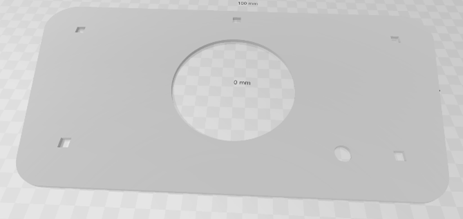
Figure 42: 3D model of steering control panel. It’s a trapezoidal shape with holes for the steering mechanism, start button, and carriage bolts that hold the panel to the fiberglass cabinet.
To make the sticker, I scanned the old panel on a flat bed (which wasn’t quite large enough so had to do it in two overlapping scans). An artist friend of mine (thanks Col!) took those and modeled them in Adobe Illustrator, and created a vector file (here). I worked with Stickermule to print the sticker, which this time (for whatever reason) required me to buy 10 of them at a time. The sticker was printed as black ink on a clear matte sticker, and done a little oversized to accommodate application/trimming.
Now, applying that custom sticker to the custom CP was no easy task, and I didn’t want to screw it up. I’ve worked with expensive repro arcade control panel overlays in the past – aligning them, using painters tape, slowly removing the backing and applying, working out the bubbles, and so on. I’ll admit that I’m pretty poor at it, and have messed up more than one application in the past. I was determined, though, this time to do it well and not have to go down any paths of removing a butchered sticker, cleaning the panel again, then re-doing. How to do it right this time?
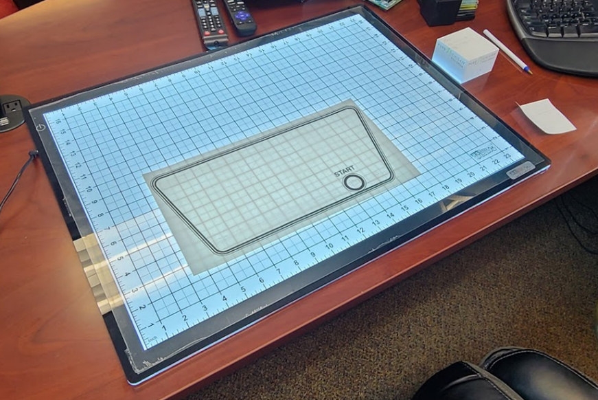
Figure 43: Sticker laying on top of the new light panel.
Well, in this case, I was thinking maybe shining some light through the panel would help me align the sticker and the panel. I dinked around with a flashlight and cell phone, propping the pieces up on random stuff around my desk – but it was goofy and not really feasible if I was going to stick this custom sticker to this custom panel and do it right the first time. I thus decided to pick up one of the new LED light tables that artists use for tracing projects. You can get smaller ones very inexpensively, but I wanted one I could also use for full-sized arcade game panels (which tend to be 24” wide) – thus I bought this one. It’s big, solid, thin, and bright – a great panel.
I laid the metal control panel on the light panel, then put the sticker (with backing still on) on top of that – trying my best to align the graphics with the positions on the panel. While there were some minor alignment issues (I think the repro sticker graphic needs some adjustments) – it was close enough. I used a pencil to mark the spot where the top bolt goes (through the line), cut a hole there, and put in a bolt. Then I used a ruler and some painters tape to align the top line in parallel with the panel top, and started pulling back the sticker backing a little at a time and attaching the sticker to the panel. It was a tricky procedure that I can’t quite describe well here, but my advice is to take your time, use a ruler, leverage painters tape when needed, and take your time (did I say take your time?). The result came out pretty solid:
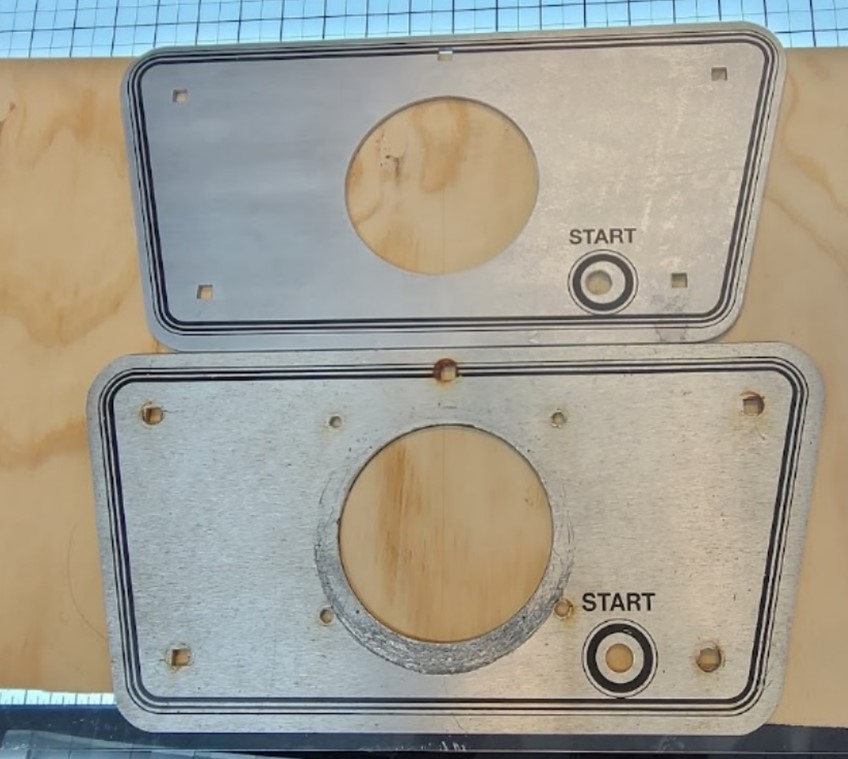
Figure 44: New panel (top) and old panel (bottom). They’re the same size, it’s just the angle the photo was taken from. Note the art is a little bit off around the start button hole, but otherwise pretty close.
Repainting the Cap
When I took another look at the pictures of other units online, I found the steering uses an Atari-logo cap in the center of the wheel:
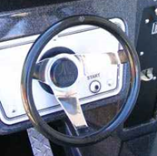
Figure 45: Picture of another ND panel from the web. Note Atari logo cap.
I went back through my pile of parts, traded out the “Kee Games” logo one I had in hand, and found a good Atari one. It’s plastic, and I washed it thoroughly – but the logo was completely faded. I found a solution at Joann Fabrics (a local craft store) in the form of a fine point silver-colored paint pen. I used the pen to carefully re-line the Atari logo, then let it dry.
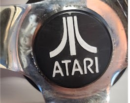
Figure 46: Relined Atari cap for steering wheel.
Steering Mechanism Spacer
With a new panel, the right mechanism, and a repainted cap, we could finally get the steering controls back together. I went to mount the mechanism – and, well, spoke too soon. and realized I was missing a spacer. Much like the metal spacer on the shifter panel, it is essential to mounting the Atari plastic control setup to a thin metal control panel. I turned to my machinist pal one more time, and we decided a 3D printed plastic spacer would be a fun solution:
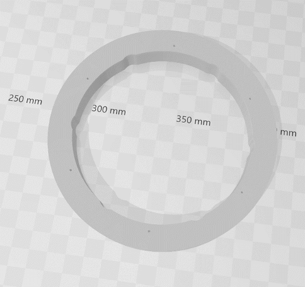
Figure 47: 3D Model of the steering wheel spacer. Note that it isn’t just a hoop; there are minor cutout areas that support the screws that pass through to the Atari plastic housing.
The file for this spacer (in case you want to print your own) is here.
Steering Wiring Harness
At this point I was able to assemble the wheel, mechanism, spacer, and optical encoder, and needed to build up the steering harness. I used the diagram shown in figure 49, the 12 pin edge connector mentioned in another section, a 6 pin Molex shell and pins, some 18 gauge stranded, and some smaller female spade quick-connects (from a little kit you can get on Amazon), and built it up. The smaller spade connectors work nicely with the standard Atari volcano switch. This bit of harnessing has to be compact, as the hole on the fiberglass cabinet for the steering mechanism isn’t huge and the wiring can’t get in the way.
For strain relief, I used an adhesive square and a zip-tie, and it all looked pretty good:
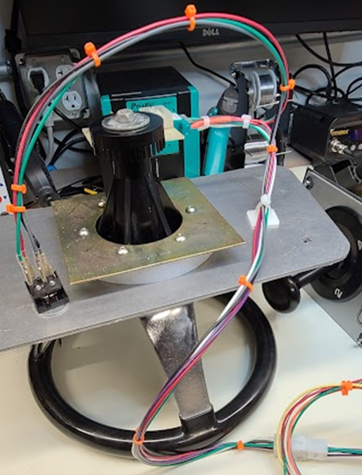
Figure 48: Mechanism assembled on panel, with wheel and harness, shown from the underside. Note the 3D printed spacer between the panel and the metal mounting plate. Also note the location of the tie-down, which turned out to be in the way when putting this through the cabinet hole. Be sure to mount the tie-down closer to the spacer vs what is shown here!
Harness
The harness that came with the converted cab was something akin to a Pole Position, not a Night Driver. I didn’t want to start from scratch, and with no hope of finding an original ND cockpit harness or there being any manual for a ND cockpit, I decided the best way was to leverage an upright harness as a starting point. I found one on Ebay for like $50, and when it arrived I have to say it was a little rough. The edge connector shell cracked in half almost immediately, and some of the pins were corroded. Studying the schematic, and knowing the cabinet, there were also some significant differences:
- The lengths of the harness weren’t quite great for the cockpit, mostly things a little long. All of the tie-down points (obviously) aren’t correct (have to move the clips).
- The upright used some lamps (the marquee, and a black light for the bezel area) that the cockpit doesn’t.
- The power connections (where it goes to the power brick/base) were a little unclear/misaligned with what the cockpit seems to have had (though unsure).
- The connector for the controls (game select, shifter, wheel, start button) is a single 15 pin intended to interface with the upright control panel. The cockpit has the shifter and game select on the shifter panel, and the wheel and start button on another – located in different spots.
As a first step toward repairing/adapting the harness, I took a new 22/44 pin edge connector shell from my stash, used the Molex 11-03-0016 pin removal tool, and transferred the pins one by one from the old cracked shell to the new one. I re-pinned the roughest ones with new pins, of course, during the swap. The most important thing here is to be really, really careful to put the pins into the right slot on the new shell – if you miss even one, you’ll be going back and having to pull a handful of them again and re-align, and that can mean damage to pins in the process (ug). Consulting the schematic in the manual (which delineates the colors of the wires on the original harnesses) also helps a lot.
After I had a new edge connector in place, I examined all of the other connectors while referencing the schematic. Using a label maker I labeled each connector shell corresponding to the connector designation in the manual OR the function of the connector (e.g. “marquee lights” etc.). Several bits were missing from the harness, and several other bits needed adapting to support the power supply change (more in another section). The biggest need was putting together a “Y” harness to break out the control panel connector into something for the separate shifter and steering wheel panels. A schematic for that is as follows:
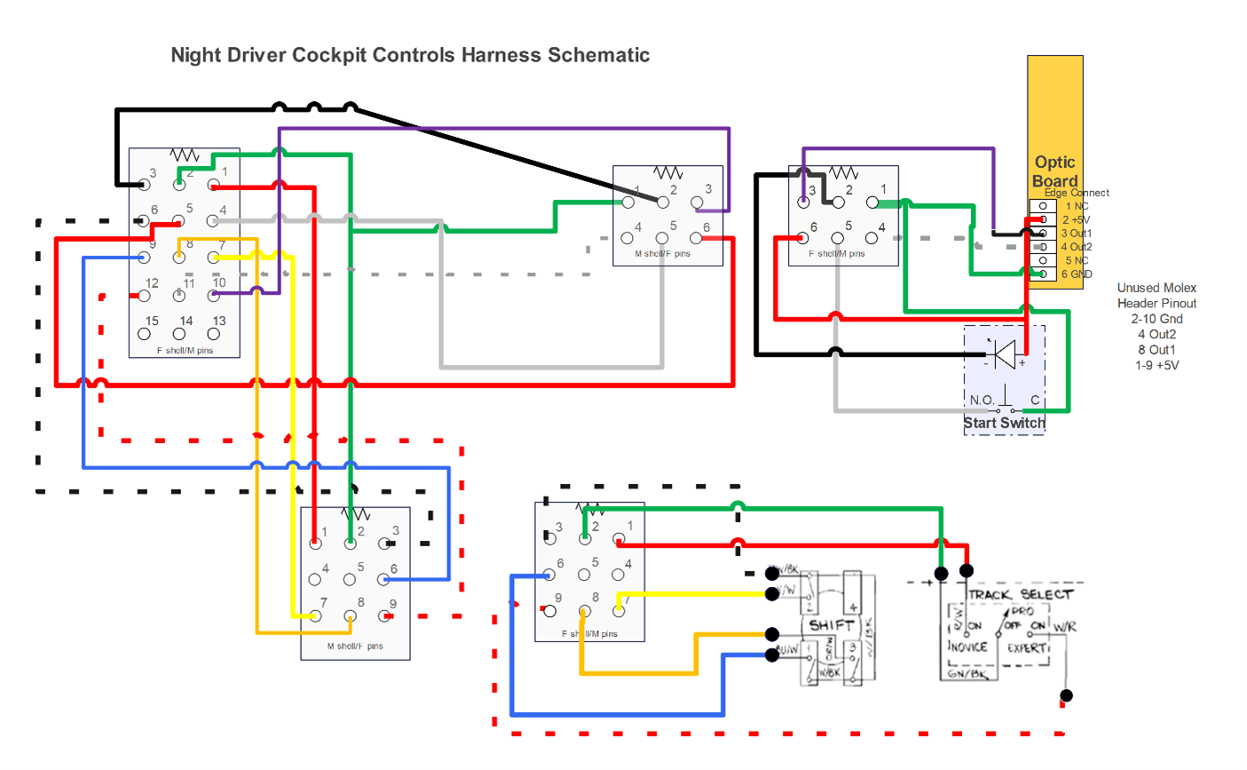
Figure 49: Controls “Y” Harness for Cockpit (and shifter/steering panel wiring)
Note that while I was stuck with a 15-pin connector from the original harness, I chose two different sized shells for the other two connectors so there would be no confusion as to what goes where when the time comes to plug things in. I also went with male pins in female shells, and vice versa. The final Y connector looks like:
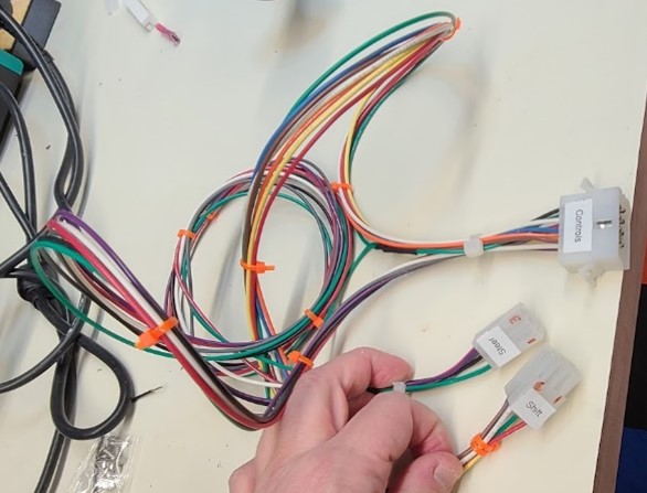
Figure 50: Y connector cable that splits from main harness into shifter panel and steering panel.
I also went through the harness, identified the simpler connectors (crimp rings and such), and replaced those using Wirefy tools and connectors. Once that was complete, I took the schematic, a multimeter, and tested the connections from the edge out to the other connectors. I didn’t find any errors, but it was reassuring to see the harness was ok and connectors were doing the right things. I set aside the harness for installation later.