I’ve always been a fan of rebuilding the original power supplies that came with these machines – linear supplies are clean, easy to work on, make sense, and just have love. As time has worn on, however, it’s becoming increasingly clear that protecting the electronics on the motherboard by ensuring good power can/should take priority. This is to say: it’s a heck of a lot easier to replace a 5V supply than it is a bunch of rams that blew because the supply voltage went south for whatever reason! This means as I work through my collection, I’ve been intermittently switching out the linears to switching supplies via adapters. I try hard not to hack the harness, but rather use proper connectors, good planning, etc… It’s worked out pretty well to date and the games are doing just fine.
WARNING: Read this but DO NOT follow in my footsteps – some mistakes were made – see later Blog post!
Building the Replacement
In the ND cockpit, the lack of the correct transformer and associated hardware, combined with the fact that I wanted the inefficient regulation off of the PCB (because it tends to cook things) – there wasn’t any other reasonable choice. I decided to use a high-quality PC power supply, which has more than enough juice for the machine. Putting it together, though, meant more than just the supply. I needed to recreate the power entrance stuff for the machine, including some fuses. A diagram is as follows:
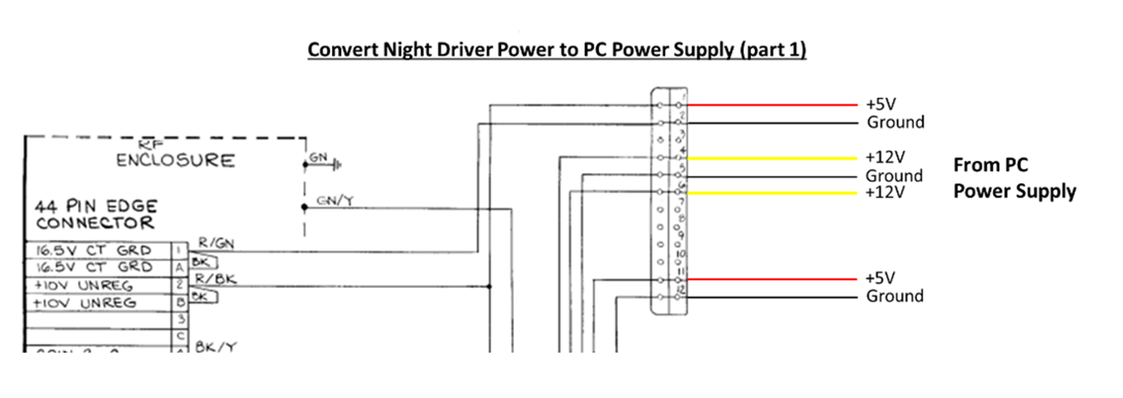
Figure 70: This diagram shows the connections from the PC power supply to the power connector on the ND harness.
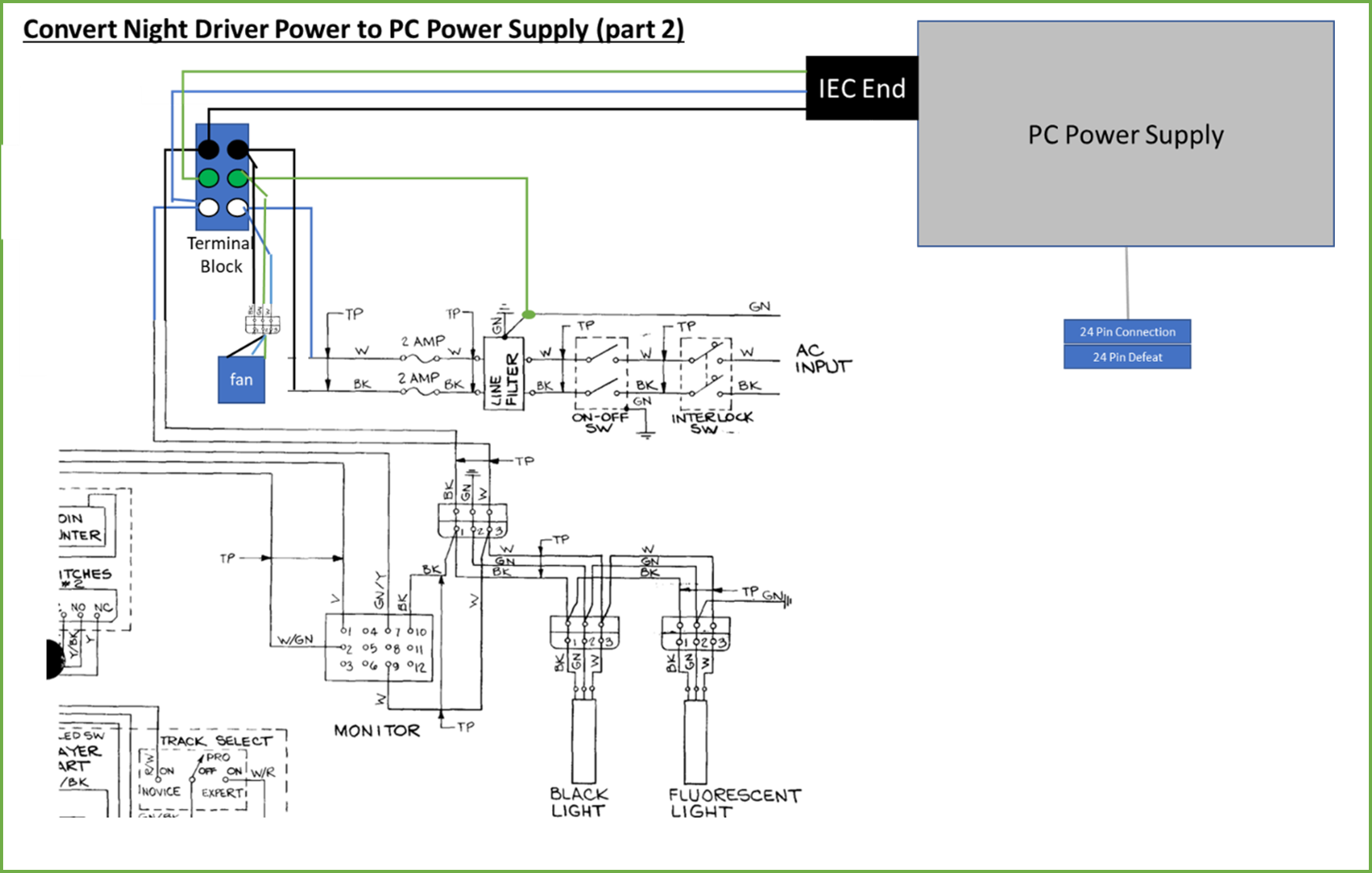
Figure 71: Showing the trail from AC input to the PC power supply and a few other AC components in the harness (the monitor and light fixtures – the latter of which aren’t actually used in the cockpit). Note the connections of 5V and 12V from the PC supply to the PCB are not shown in this diagram. Also note where I added a fan (discussed in another section).
The parts list for this little operation was:
- PC Power Supply (500W, but that’s probably overkill)
- PC Power Supply bridge tool
- Dual fuse holder (for 3AG 0.25”x1.25” fuses)
- Power line filter (for 125V input, 10A)
- Terminal block
- Mounting bracket for supply (3D printed or bought)
- Fuses – 2A, 120V, 3AG glass, slow-blo
- 6’ standard PC power cord with IEC connector
- Mounting board (1/2” plywood)
- Wirefy crimp connectors, miscellaneous
- Miscellaneous screws, P-clips, wire ties
I didn’t take enough photos while constructing this, but I followed the schematic, tried to lay things out cleanly and neatly, and provide some elbow room. I used good-quality crimp connectors (the Wirefy stuff) and P-clips to tie things down. The AC gets to the PC supply via a butchered IEC power cable that connects to the terminal block. The bridge tool is attached to the 24 pin connector on the supply to as to make sure it is “on” when the supply gets 120V (if you aren’t familiar with that jumper on those supplies, see this article).
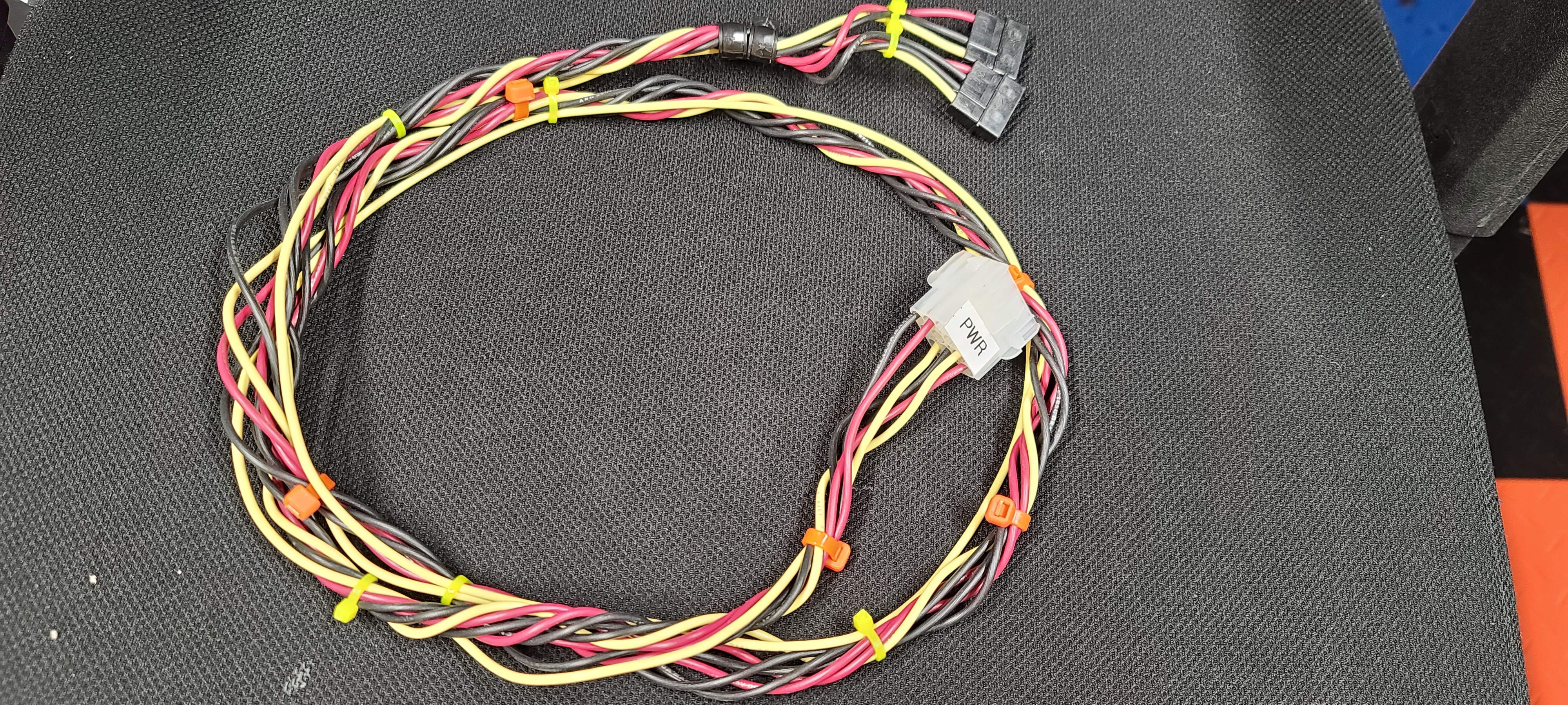
The +5, +12, and Ground connections are taken from some of the drive connectors. Did I just chop them off and solder on some extensions? Hell no – we’re classy, folks. We used matching Molex connectors to attach to the four pin drive connectors. I went with this because if the PC supply dies, for whatever reason, I want to be able to swap it for a new one with no harness chopping. In fact, one of the biggest advantages of converting these games to switching is that, in case of supply failure, you can swap in a working supply in minutes and be back up and running. In any case, the matching Molex connectors ran via some good stranded 16-gauge wire to another Molex shell that mated with the 12 pin power connector on the harness that would normally come from the transformer.
I should also mention: mounting a PC supply to a board isn’t always the easiest. There are brackets you can buy online for this sort of task, but a friend of mine was messing with 3D printed versions, and I ended up using this. It’s not perfect (a little weak) but should be fine just to hold that supply in place. It probably also would have been easier had I bought a modular supply and not have all the spare cable/connectors taking up room, but they were significantly more expensive. Those modular supplies cost like 50% more, and that’s a lot more than a wire tie to keep the cables at bay. 😊
To give you an idea of what the first pass looked like:
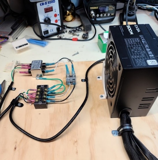
Figure 72: First prototype of the power board. Big, but clean!
I was pretty proud of myself – until I went to mount the board in the machine. Somehow I didn’t actually think about the packaging/space available in the back of that fiberglass machine – it was way shallower than I remembered. This meant I had to take the board back to the bench, unmount, some parts, slice the base board in half, then re-arrange and mount a few things. It was a hassle, but I eventually got there.
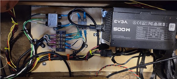
Figure 73: Power board mounted in machine. You can see the filter, terminal block, double fuse block, PC supply, and 3D printed mount (white piece).
Integrating into the Machine
The new cut-down board with the supply and related components was secured to the wood base of the machine using self-tapping screws. Of course, there are cabinet-based components that form the rest of the power circuit (the power cord, interlock switch, power switch, and associated harnessing):
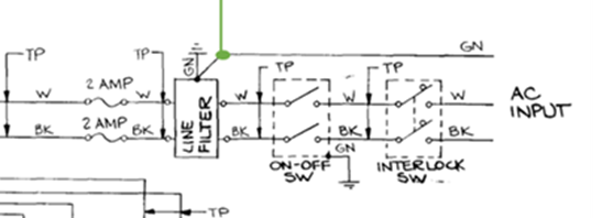
Figure 74: AC input circuit of machine
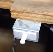
Figure 75: Interlock attached to bracket/monitor shelf. When the back door is closed, the game can power up – but if open, the interlock kills the AC power.
Part of the harness and power switch were missing from the machine, and the interlock looked super rough. I dug through my stash and came up with a new DPST switch (like this one) that fit the metal mounting bracket already installed in the machine, and also dug out a new interlock (this one) and a new interlock mounting bracket (this one). The power cable installed in the machine wasn’t great but wasn’t terrible – so I left that in place to use. Using 14 gauge stranded wire and some crimp connectors, I went ahead and made the missing parts of the harness piece. Of all the stuff in the machine you absolutely 100% want to make sure you do a good job here, as 120VAC shorts or problems tend not to be very pretty. All of this stuff got mounted in the cabinet, and I replaced the original Atari plastic cover over the switch on the inside of the cabinet. Why is there a cover there? It is there to protect folks from touching a live 120VAC line if they are rooting around inside the machine while it is still plugged in. That’s also the reason I chose a covered terminal block on the power board – a little extra safety never hurts.
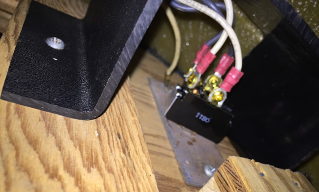
Figure 76: Installed power switch and cover, as photographed from inside/below. Note the metal mounting plate for the switch, and the plastic safety cover. Also note how crimp connectors were used in conjunction with the switch terminal screws to ensure the wires didn’t come off too easily.
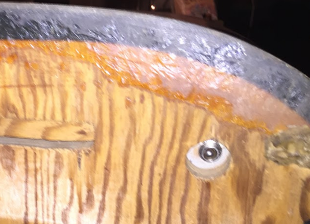
Figure 77: Power switch as seen from outside the cabinet.
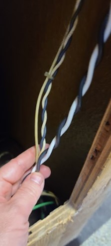
Figure 78: Part of AC power harness running vertically along rear inside of the machine.
Note that the AC power line harness stuff above all ties into the power board at the inputs to the power filter. On the part that attaches to the logic, it was attached a couple of the 4 pin Molex connectors on the PC supply to the adapter that ran to the 12-pin game power connector per Figure 79.
EDIT: Before you replicate the power PCB per above, check out the troubleshooting section in a later entry. For unknown reasons, this didn’t work, and I changed the plan….