As I mentioned, the monitor in the machine that I picked up was a G07, which is a color 19” typical of a lot of games of that era. The ND cockpit, from everything I could tell, used the standard 23” B&W monitor. I went to my stash and pulled a spare Wells Gardner 22V1001 and put it on the benchtop. It was a bit of a mess – dirty, loose flyback HV anode line, mostly original caps – and a weird mod or two that must have happened decades ago. I was glad to find the monitor, but this was going to be a project…
Recapping and Other Fixes
I ordered a cap kit from arcadepartsandrepair.com, including caps for the “big metal can.” I also ordered a 2N5632 voltage regulator and a BU208A HOT (horizontal output transistor) from the same place. I didn’t even bother plugging it in, as so many things looked flaky that I didn’t want to risk additional damage on power-up. I discharged the tube anyway by attaching my screwdriver-based tool to the chassis and then up under the anode (see THIS video for tips, in case you’re unfamiliar), then carefully pulled the main PCB off the chassis using a plier (to squeeze the plastic retention clips) and a screwdriver (to help pry from the underside). You have to be careful with these boards as they can bend easily, you can hurt the early pin/header situation on one or more of the sides, and so on. The nice thing, though, is that having the board away from the rest of the chassis makes it a pleasure to work on. I guess I should also mention that you have to pull the neck connector at this time also – with your hands, just be gentle!
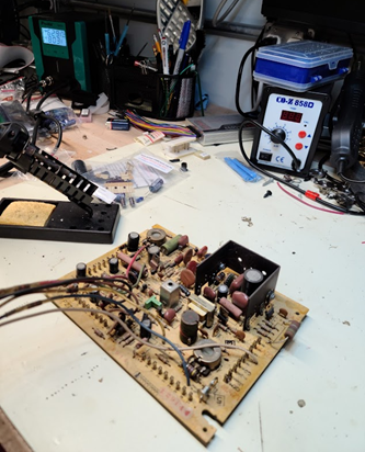
Figure 5: 22V1001 motherboard on benchtop
I recapped the monitor PCB with the kit, taking care to ensure proper polarity (of course) of the electrolytics. I’m a big fan of the SS-331H desoldering station, which you can order on Amazon for $200+ or Aliexpress for roughly $120 including shipping. It isn’t perfect, but you get used to it and it really does make quick work of this sort of project. I also use a bit of this liquid flux on every connection before desoldering, just to help things flow (these are old connections, dude!). In case you’re not familiar, you can get that large bottle of liquid flux, get some small squeeze bottles with needle caps, and have a really convenient dispenser anytime you need some:
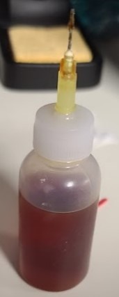
Figure 6: Flux in a needle-tip dispensing bottle. Works like a charm!
The caps came out cleanly and easily, and all was fine. I also had to replace a few on the chassis itself, which meant putting down a towel on the workbench, laying the monitor on its face, then replacing the key caps under the metal chassis. BTW, if you’re not familiar with the sort of point-to-point connectivity in older monitors or radios, or even if you are, I deeply suggest you take a bunch of photos before starting any changes/replacements – it’s just too easy to forget which connection goes where, and having the photos makes it very easy to double-check your work without going back to the schematics, tracing, etc..
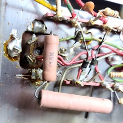
Figure 7: What I mean by point-to-point wiring. Note the square hole in the metal on the left hand side of the image – that’s where the metal can connections come through the chassis.
The Big Metal Can (and More)
The worst part of the cap job, as it always seems to be with these older monitors, is the giant metal can that is a multi-cap. Back in the day this was a great solution to getting a bunch of higher value caps together in one nice package, but they aren’t really an easily sourced thing (though I recently discovered there are modern places making similar stuff – and arcadeshop.com started selling drop in replacements). I was thus left in the familiar position of jury-rigging the metal can replacement. I tried something new this time, though: getting a piece of ½” PVC and an adapter and building a simple “replacement” for the can with the caps stuffed inside. The main constraint was making sure the adapter could fit in the existing hole on the chassis (didn’t want to expand) and used an adapter I could easily get at Lowes. I basically attached wire pigtails to the caps, stuffed them into the tube, and went from there. It *almost* worked, except the largest of the caps was too big a diameter to fit in the PVC and thus ended up as the “top hat” of the replacement. I should mention I did use both an adapter nut and a little hot glue to ensure the new PVC can was solidly in place before soldering the wires underneath. Yeah, I’m sure there are better/easier methods, but it worked…
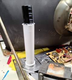
Figure 8: PVC-based metal can replacement. Caps are stuffed into it, with one cap glued to the top.
As I mentioned before, I’m also a believer that I might as well replace the voltage regulator and the HOT while I’m working on it, as these two parts have seen an awful lot over the years of use. In this chassis both are socketed, so you can unscrew them and they will pop out just fine. I cleaned up the old thermal compound with some alcohol, sprayed the sockets with contact cleaner, put down a nice new layer of thermal paste and a mica insulator, and installed both TO-3 parts.
Flyback Diode Issue?
At this point I also took a look at the flyback, and the wire coming out of it seemed loose at the flyback itself. When I disconnected the anode from the tube, the whole thing fell off. If you look closely at this monitor, you note that there is a high voltage diode that sits in a connector at the output of the secondary, and the one end of the flexible rubber-coated wire that goes to the tube is connected at the other end of the diode. All we had to do here was spray a little contact cleaner on the end of the diode, and into the receiving socket on the flyback, and get it back in there. I used a little hot glue to keep it in that socket and ensure it didn’t just fall out again, and then I reinstalled the anode cup end into the tube.
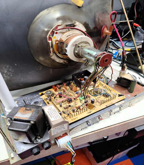
Figure 9: Back of monitor, reassembled, with test harness attached.
Testing and Troubleshooting
With everything back together, I needed to test this monitor. Fortunately, one of the fun features of the early B&W monitors is that all of their connections (power, video, audio) run through a single Molex connector. I thus went and built a simple test harness (see schematic) that would let me power it up and give it a composite signal (these B&W monitors always used composite). An old portable DVD player (with the semi-embarrassing film “Star Trek Beyond”) provided a reasonable signal source. Note that these monitors DO NOT require an isolation transformer. Also, I use a mirror on my benchtop so I can work on the back of the monitor while seeing what’s coming up on the CRT (if you need one of these, I suggest a cheap plexi mirror in a frame from any home goods type store). The first test was good, but not great. The picture was there but fuzzy, and not very bright.
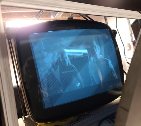
Figure 10: Star Trek Beyond – not a phenom test pattern, but it worked. Note how I view the monitor indirectly through a mirror so I can have access to the controls on my bench/tweak it in real time.
I thus started running through adjustments to the monitor (all specified in the manual) – including the B+ adjustment, which turned out to be almost dead-on from the start. I cleaned all the pots with contact cleaner, replaced some of the more problematic looking thumbwheels (those things oxidize, wiper becomes bad, and it’s easiest to replace them), and did some more tuning. It was at this point that the monitor went bright white – had a raster, but no picture, and was much brighter than before. I couldn’t tell what I had done wrong, so I got out the schematics, my Fluke 77 meter, and started tracing….
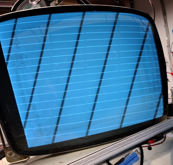
Figure 11: Star Trek gone, white retrace and raster only — what’s up?!?!!?
….and what I found was a lack of 73v at a couple different places. I thought for sure it was going to be capacitor C110 (1uF, 630V), which I had neglected to replace – so I ordered a new cap, waited a week, replaced it, and tried again. Still no dice – just a white raster, no picture. I finally traced, step by step, back to the source of the voltage – one of the pins on the bottom of the flyback. This is when I realized the wire on the flyback at that pin was loose (!!) even though it looked good and well-soldered. I thus heated that connection up, added a little solder, set the monitor back up, and – WOW – all fixed! Now I had a well-synced picture, it was reasonably bright, and all was good. I tweaked the adjustments one more time, then set the monitor aside.